This extraction supports search. Read the original page for complete notation and layout.
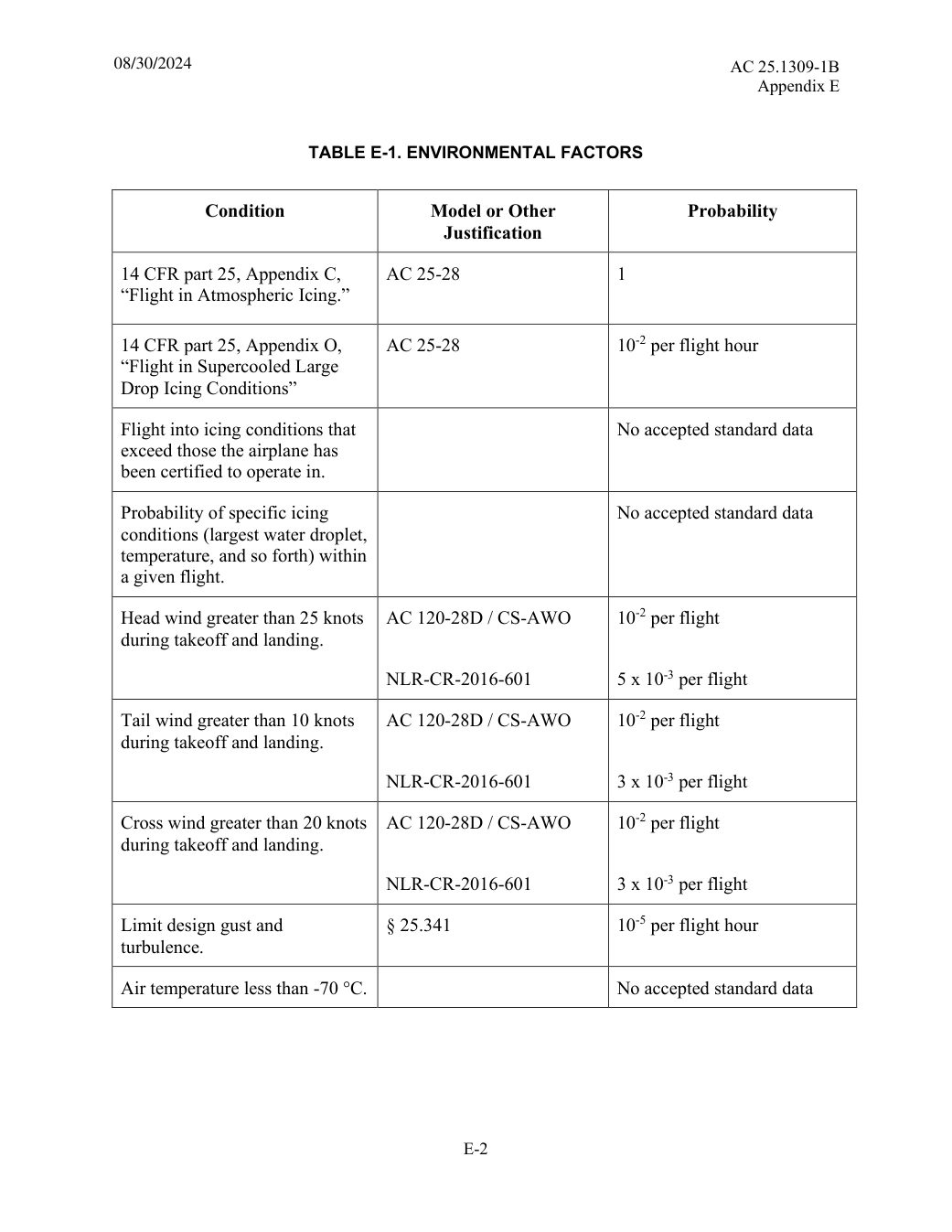
TABLE E-1. ENVIRONMENTAL FACTORS

Condition Model or Other Justification Probability

14 CFR part 25, Appendix C, “Flight in Atmospheric Icing.” AC 25-28 1

AC 25-28 10-2 per flight hour

14 CFR part 25, Appendix O, “Flight in Supercooled Large Drop Icing Conditions”

No accepted standard data

Flight into icing conditions that exceed those the airplane has been certified to operate in.

No accepted standard data

Probability of specific icing conditions (largest water droplet, temperature, and so forth) within a given flight.

10-2 per flight

Head wind greater than 25 knots during takeoff and landing. AC 120-28D / CS-AWO

NLR-CR-2016-601

5 x 10⁻³ per flight

10-2 per flight

Tail wind greater than 10 knots during takeoff and landing. AC 120-28D / CS-AWO

NLR-CR-2016-601

3 x 10⁻³ per flight

10-2 per flight

Cross wind greater than 20 knots during takeoff and landing. AC 120-28D / CS-AWO

NLR-CR-2016-601

3 x 10⁻³ per flight

Limit design gust and turbulence. § 25.341 10-5 per flight hour

Air temperature less than -70 °C. No accepted standard data
Saved from the FAA on November 16, 2026. All original pages are retained. Engineering explanations are presented separately below.
Aerospace Consulting / Engineering perspective
Connect the analysis to the design.
A useful assessment explains why the architecture meets the safety objectives, what assumptions it relies on, and how those assumptions will be verified. We use the guidance to structure the questions and evidence around the actual system.
01 / Define the failure conditions
Begin with functions and effects.
Describe the operating context, affected functions, crew response and interactions with other systems. Carry the resulting safety objectives into the architecture and requirements.
Explain monitoring, fault containment and common causes. Examine significant latent failures and the assumptions about how long a failure can remain present.
Connect the analysis to the implemented configuration, justified data, verification results, crew actions and maintenance requirements. Keep unresolved assumptions visible until they are closed.
Our practice uses ARP4761A and ARP4754B to organise safety assessment and systems development work. This AC refers to ARP 4761 and ARP 4754 without revision letters. Its references alone do not establish acceptance of a particular revision for a programme.
75 original pages. 55 pages have reviewed text reflows. Original-first pages retain the source layout, with extracted text available for finding words.
A focused review, an agreed assessment package or ongoing support alongside your team. We can agree the relevant inputs and scope in the initial conversation.
This opens your email application.
Start a conversation
Tell us about your programme, the system you are developing and the support you need.
We can agree a focused use-case review, a defined evidence package or ongoing programme support.
This opens your email application.
Specialist aerospace expertise
Aerospace Consulting is led by Hussein Khimji, an FAA Designated Engineering Representative in systems and equipment, with a focus on system safety, flight controls and avionics.
We work with aircraft developers and systems suppliers to connect technical decisions, safety assessments and certification evidence.
This is the proposed introduction. The full About page will add your approved biography and associate expertise.
Systems engineering & development assurance
Tell us about the aircraft or system, its intended function, stage of development and the support you need.