Certification of Normal Category Rotorcraft — Changes 1–9
Normal category rotorcraft guidance with Changes 1–9 incorporated. Search the complete AC or start with the system safety, flight controls and instrument-flight guidance.
This source includes guidance for different amendments of Part 27. Match the guidance to the aircraft’s agreed certification basis: the 27.1309 entries for Amendments 27-21, 27-46 and 27-51 are separate. The base AC was issued on 30 September 1999; Change 9 is dated 23 June 2023. The FAA catalogue’s 30 September 2008 date is not the date of the latest change.
The source, within reach.
Search within this AC, jump to a source page, or download the complete saved publication.
This extraction supports search. Read the original page for complete notation and layout.
AC 27-1B                                                                  9/30/99


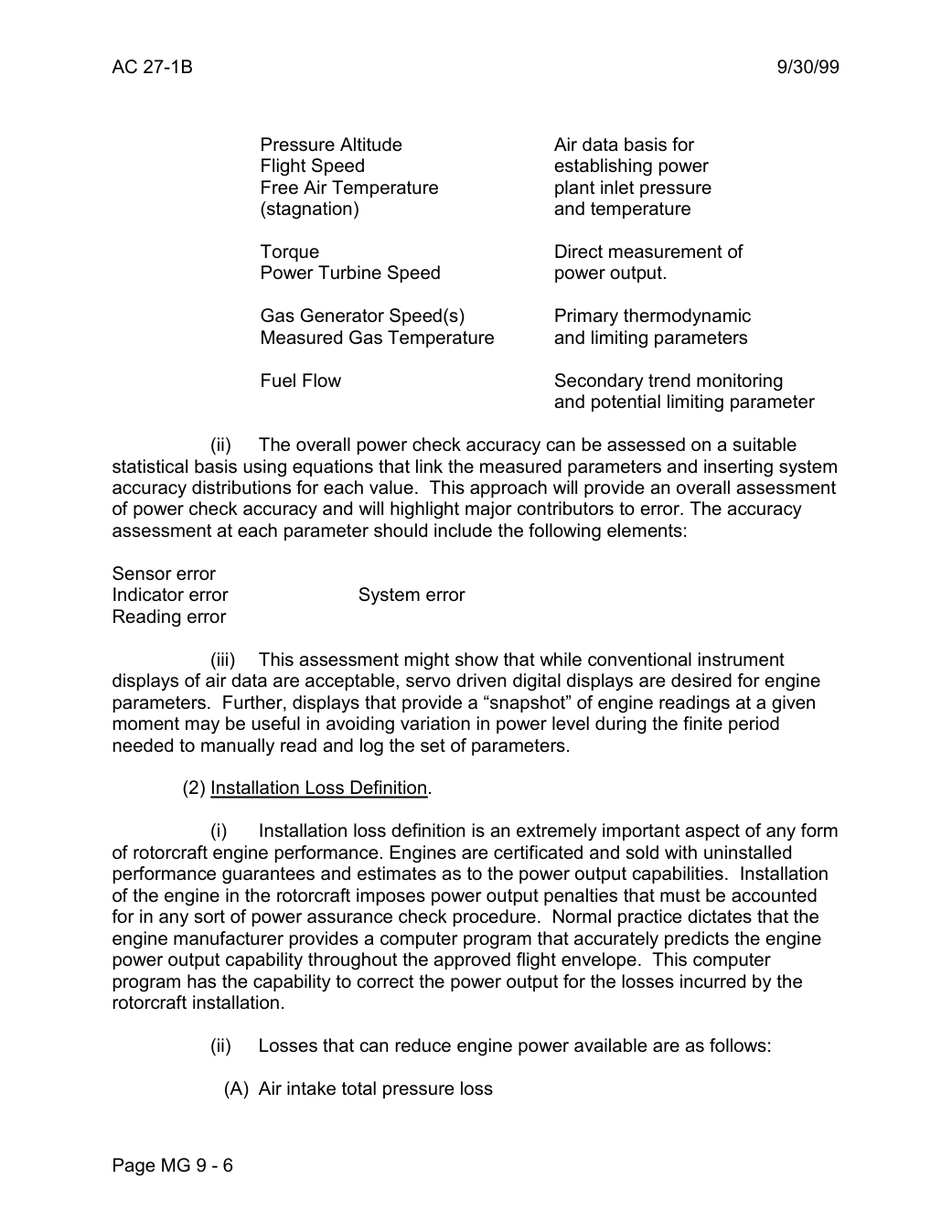
                Pressure Altitude                    Air data basis for
                    Flight Speed                       establishing power
               Free Air Temperature              plant inlet pressure
                  (stagnation)                   and temperature

               Torque                             Direct measurement of
              Power Turbine Speed           power output.

             Gas Generator Speed(s)          Primary thermodynamic
              Measured Gas Temperature      and limiting parameters

                Fuel Flow                     Secondary trend monitoring
                                          and potential limiting parameter

                   (ii)   The overall power check accuracy can be assessed on a suitable
statistical basis using equations that link the measured parameters and inserting system
accuracy distributions for each value. This approach will provide an overall assessment
of power check accuracy and will highlight major contributors to error. The accuracy
assessment at each parameter should include the following elements:

Sensor error
Indicator error             System error
Reading error

                    (iii)   This assessment might show that while conventional instrument
displays of air data are acceptable, servo driven digital displays are desired for engine
parameters. Further, displays that provide a “snapshot” of engine readings at a given
moment may be useful in avoiding variation in power level during the finite period
needed to manually read and log the set of parameters.

         (2) Installation Loss Definition.

                  (i)    Installation loss definition is an extremely important aspect of any form
of rotorcraft engine performance. Engines are certificated and sold with uninstalled
performance guarantees and estimates as to the power output capabilities. Installation
of the engine in the rotorcraft imposes power output penalties that must be accounted
for in any sort of power assurance check procedure. Normal practice dictates that the
engine manufacturer provides a computer program that accurately predicts the engine
power output capability throughout the approved flight envelope. This computer
program has the capability to correct the power output for the losses incurred by the
rotorcraft installation.

                   (ii)   Losses that can reduce engine power available are as follows:

              (A) Air intake total pressure loss


Page MG 9 - 6
Saved from the FAA on November 17, 2026. All original pages are retained. Engineering explanations are presented separately below.
Aerospace Consulting / Engineering perspective
Start with the certification basis and the function.
Identify the applicable amendment before selecting the safety guidance. Connect intended functions and operating conditions to failure conditions, architecture decisions, common-cause considerations, verification and limitations. For flight controls and IFR work, carry the relevant 27.672, 27.1329 and Appendix B assumptions into the system safety and compliance evidence.
1196 original pages. 0 pages have reviewed text reflows. Original-first pages retain the source layout, with extracted text available for finding words.
A focused review, an agreed assessment package or ongoing support alongside your team. We can agree the relevant inputs and scope in the initial conversation.
This opens your email application.
Start a conversation
Tell us about your programme, the system you are developing and the support you need.
We can agree a focused use-case review, a defined evidence package or ongoing programme support.
This opens your email application.
Specialist aerospace expertise
Aerospace Consulting is led by Hussein Khimji, an FAA Designated Engineering Representative in systems and equipment, with a focus on system safety, flight controls and avionics.
We work with aircraft developers and systems suppliers to connect technical decisions, safety assessments and certification evidence.
This is the proposed introduction. The full About page will add your approved biography and associate expertise.
Systems engineering & development assurance
Tell us about the aircraft or system, its intended function, stage of development and the support you need.