
Original FAA page, including its printed amendment and change markings. Extracted words support search; text reflow has not been reviewed.
AC 27-1B · 843Open saved PDF here ↗
Extracted text for finding words
This extraction supports search. Read the original page for complete notation and layout.
2/27/2014                                      AC 27-1B, Chg 4


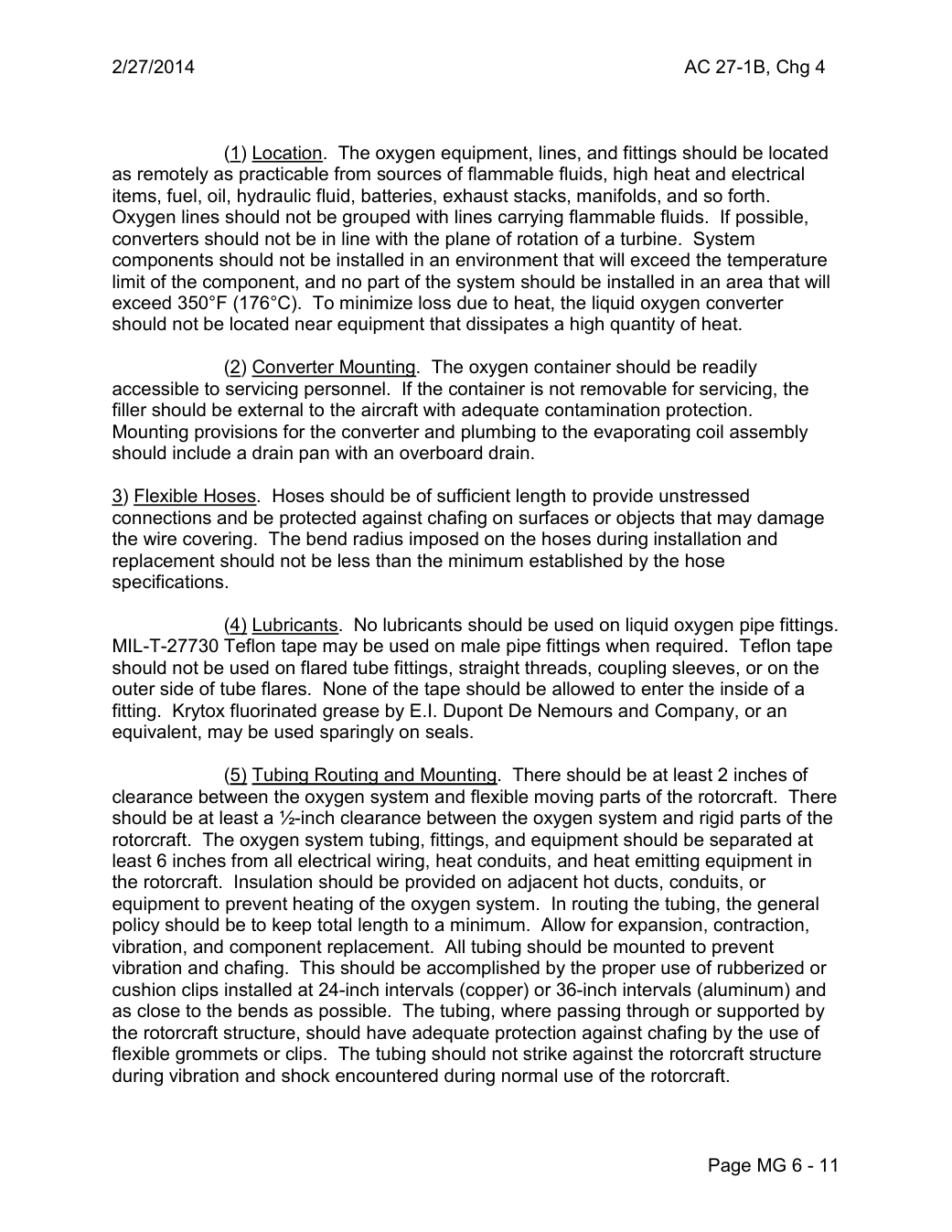
               (1) Location. The oxygen equipment, lines, and fittings should be located
as remotely as practicable from sources of flammable fluids, high heat and electrical
items, fuel, oil, hydraulic fluid, batteries, exhaust stacks, manifolds, and so forth.
Oxygen lines should not be grouped with lines carrying flammable fluids.  If possible,
converters should not be in line with the plane of rotation of a turbine. System
components should not be installed in an environment that will exceed the temperature
limit of the component, and no part of the system should be installed in an area that will
exceed 350°F (176°C). To minimize loss due to heat, the liquid oxygen converter
should not be located near equipment that dissipates a high quantity of heat.

               (2) Converter Mounting. The oxygen container should be readily
accessible to servicing personnel.  If the container is not removable for servicing, the
filler should be external to the aircraft with adequate contamination protection.
Mounting provisions for the converter and plumbing to the evaporating coil assembly
should include a drain pan with an overboard drain.

3) Flexible Hoses. Hoses should be of sufficient length to provide unstressed
connections and be protected against chafing on surfaces or objects that may damage
the wire covering. The bend radius imposed on the hoses during installation and
replacement should not be less than the minimum established by the hose
specifications.

               (4) Lubricants. No lubricants should be used on liquid oxygen pipe fittings.
MIL-T-27730 Teflon tape may be used on male pipe fittings when required. Teflon tape
should not be used on flared tube fittings, straight threads, coupling sleeves, or on the
outer side of tube flares. None of the tape should be allowed to enter the inside of a
fitting. Krytox fluorinated grease by E.I. Dupont De Nemours and Company, or an
equivalent, may be used sparingly on seals.

               (5) Tubing Routing and Mounting. There should be at least 2 inches of
clearance between the oxygen system and flexible moving parts of the rotorcraft. There
should be at least a ½-inch clearance between the oxygen system and rigid parts of the
rotorcraft. The oxygen system tubing, fittings, and equipment should be separated at
least 6 inches from all electrical wiring, heat conduits, and heat emitting equipment in
the rotorcraft. Insulation should be provided on adjacent hot ducts, conduits, or
equipment to prevent heating of the oxygen system. In routing the tubing, the general
policy should be to keep total length to a minimum. Allow for expansion, contraction,
vibration, and component replacement. All tubing should be mounted to prevent
vibration and chafing. This should be accomplished by the proper use of rubberized or
cushion clips installed at 24-inch intervals (copper) or 36-inch intervals (aluminum) and
as close to the bends as possible. The tubing, where passing through or supported by
the rotorcraft structure, should have adequate protection against chafing by the use of
flexible grommets or clips. The tubing should not strike against the rotorcraft structure
during vibration and shock encountered during normal use of the rotorcraft.


                                                       Page MG 6 - 11