Certification of Normal Category Rotorcraft — Changes 1–9
Normal category rotorcraft guidance with Changes 1–9 incorporated. Search the complete AC or start with the system safety, flight controls and instrument-flight guidance.
This source includes guidance for different amendments of Part 27. Match the guidance to the aircraft’s agreed certification basis: the 27.1309 entries for Amendments 27-21, 27-46 and 27-51 are separate. The base AC was issued on 30 September 1999; Change 9 is dated 23 June 2023. The FAA catalogue’s 30 September 2008 date is not the date of the latest change.
The source, within reach.
Search within this AC, jump to a source page, or download the complete saved publication.
This extraction supports search. Read the original page for complete notation and layout.
2/27/2014                                      AC 27-1B, Chg 4


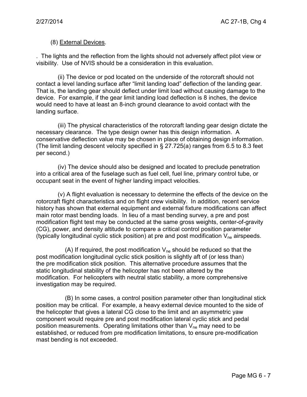
      (8) External Devices.

. The lights and the reflection from the lights should not adversely affect pilot view or
visibility. Use of NVIS should be a consideration in this evaluation.

             (ii) The device or pod located on the underside of the rotorcraft should not
contact a level landing surface after “limit landing load” deflection of the landing gear.
That is, the landing gear should deflect under limit load without causing damage to the
device. For example, if the gear limit landing load deflection is 8 inches, the device
would need to have at least an 8-inch ground clearance to avoid contact with the
landing surface.

              (iii) The physical characteristics of the rotorcraft landing gear design dictate the
necessary clearance. The type design owner has this design information. A
conservative deflection value may be chosen in place of obtaining design information.
(The limit landing descent velocity specified in § 27.725(a) ranges from 6.5 to 8.3 feet
per second.)

          (iv) The device should also be designed and located to preclude penetration
into a critical area of the fuselage such as fuel cell, fuel line, primary control tube, or
occupant seat in the event of higher landing impact velocities.

         (v) A flight evaluation is necessary to determine the effects of the device on the
rotorcraft flight characteristics and on flight crew visibility. In addition, recent service
history has shown that external equipment and external fixture modifications can affect
main rotor mast bending loads. In lieu of a mast bending survey, a pre and post
modification flight test may be conducted at the same gross weights, center-of-gravity
(CG), power, and density altitude to compare a critical control position parameter
(typically longitudinal cyclic stick position) at pre and post modification Vne airspeeds.

           (A) If required, the post modification Vne should be reduced so that the
post modification longitudinal cyclic stick position is slightly aft of (or less than)
the pre modification stick position. This alternative procedure assumes that the
static longitudinal stability of the helicopter has not been altered by the
modification. For helicopters with neutral static stability, a more comprehensive
investigation may be required.

           (B) In some cases, a control position parameter other than longitudinal stick
position may be critical. For example, a heavy external device mounted to the side of
the helicopter that gives a lateral CG close to the limit and an asymmetric yaw
component would require pre and post modification lateral cyclic stick and pedal
position measurements. Operating limitations other than Vne may need to be
established, or reduced from pre modification limitations, to ensure pre-modification
mast bending is not exceeded.


                                                        Page MG 6 - 7
Saved from the FAA on November 17, 2026. All original pages are retained. Engineering explanations are presented separately below.
Aerospace Consulting / Engineering perspective
Start with the certification basis and the function.
Identify the applicable amendment before selecting the safety guidance. Connect intended functions and operating conditions to failure conditions, architecture decisions, common-cause considerations, verification and limitations. For flight controls and IFR work, carry the relevant 27.672, 27.1329 and Appendix B assumptions into the system safety and compliance evidence.
1196 original pages. 0 pages have reviewed text reflows. Original-first pages retain the source layout, with extracted text available for finding words.
A focused review, an agreed assessment package or ongoing support alongside your team. We can agree the relevant inputs and scope in the initial conversation.
This opens your email application.
Start a conversation
Tell us about your programme, the system you are developing and the support you need.
We can agree a focused use-case review, a defined evidence package or ongoing programme support.
This opens your email application.
Specialist aerospace expertise
Aerospace Consulting is led by Hussein Khimji, an FAA Designated Engineering Representative in systems and equipment, with a focus on system safety, flight controls and avionics.
We work with aircraft developers and systems suppliers to connect technical decisions, safety assessments and certification evidence.
This is the proposed introduction. The full About page will add your approved biography and associate expertise.
Systems engineering & development assurance
Tell us about the aircraft or system, its intended function, stage of development and the support you need.