Certification of Normal Category Rotorcraft — Changes 1–9
Normal category rotorcraft guidance with Changes 1–9 incorporated. Search the complete AC or start with the system safety, flight controls and instrument-flight guidance.
This source includes guidance for different amendments of Part 27. Match the guidance to the aircraft’s agreed certification basis: the 27.1309 entries for Amendments 27-21, 27-46 and 27-51 are separate. The base AC was issued on 30 September 1999; Change 9 is dated 23 June 2023. The FAA catalogue’s 30 September 2008 date is not the date of the latest change.
The source, within reach.
Search within this AC, jump to a source page, or download the complete saved publication.
This extraction supports search. Read the original page for complete notation and layout.
AC 27-1B, Chg 7                                                       2/4/2016


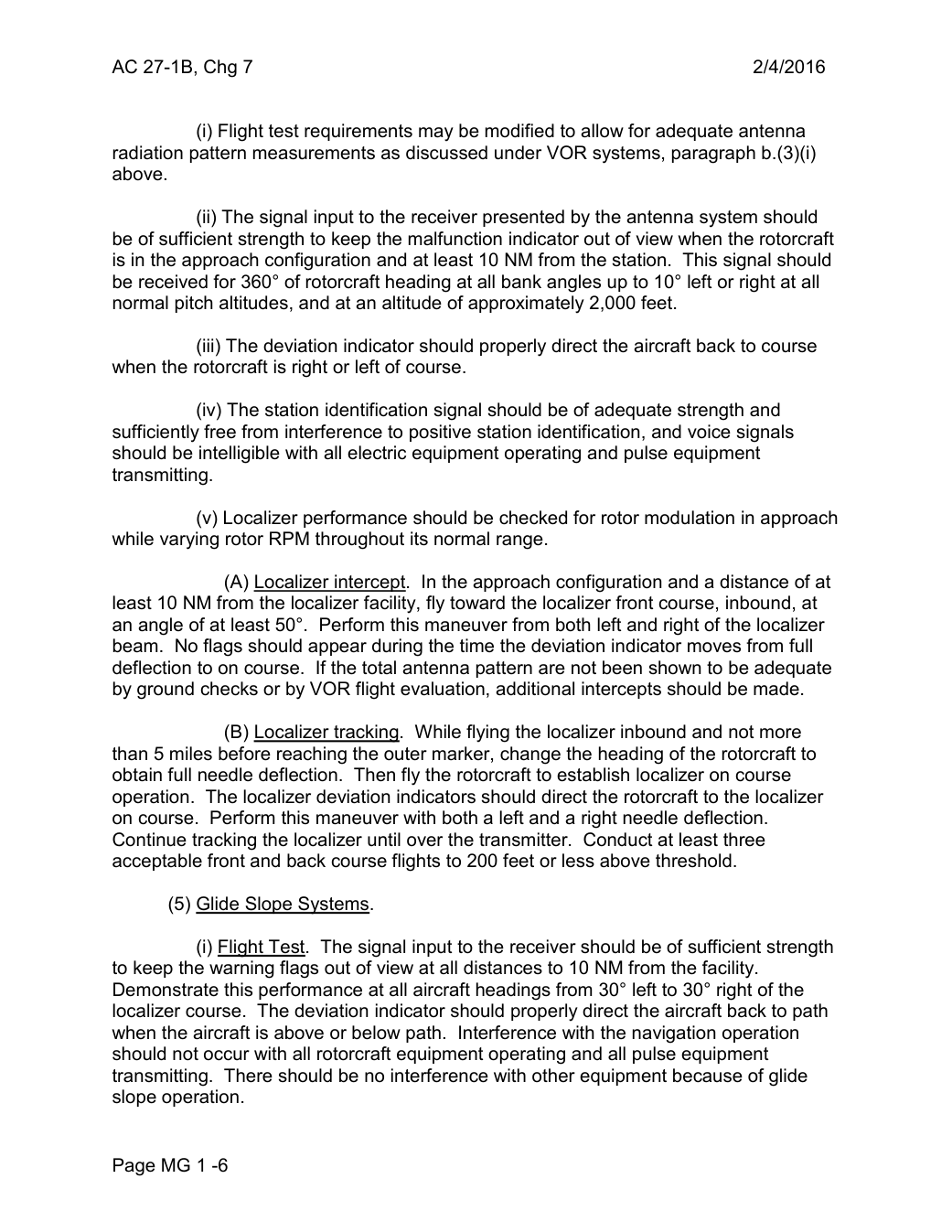
               (i) Flight test requirements may be modified to allow for adequate antenna
radiation pattern measurements as discussed under VOR systems, paragraph b.(3)(i)
above.

                (ii) The signal input to the receiver presented by the antenna system should
be of sufficient strength to keep the malfunction indicator out of view when the rotorcraft
is in the approach configuration and at least 10 NM from the station. This signal should
be received for 360° of rotorcraft heading at all bank angles up to 10° left or right at all
normal pitch altitudes, and at an altitude of approximately 2,000 feet.

                 (iii) The deviation indicator should properly direct the aircraft back to course
when the rotorcraft is right or left of course.

             (iv) The station identification signal should be of adequate strength and
sufficiently free from interference to positive station identification, and voice signals
should be intelligible with all electric equipment operating and pulse equipment
transmitting.

            (v) Localizer performance should be checked for rotor modulation in approach
while varying rotor RPM throughout its normal range.

              (A) Localizer intercept. In the approach configuration and a distance of at
least 10 NM from the localizer facility, fly toward the localizer front course, inbound, at
an angle of at least 50°. Perform this maneuver from both left and right of the localizer
beam. No flags should appear during the time the deviation indicator moves from full
deflection to on course.  If the total antenna pattern are not been shown to be adequate
by ground checks or by VOR flight evaluation, additional intercepts should be made.

              (B) Localizer tracking. While flying the localizer inbound and not more
than 5 miles before reaching the outer marker, change the heading of the rotorcraft to
obtain full needle deflection. Then fly the rotorcraft to establish localizer on course
operation. The localizer deviation indicators should direct the rotorcraft to the localizer
on course. Perform this maneuver with both a left and a right needle deflection.
Continue tracking the localizer until over the transmitter. Conduct at least three
acceptable front and back course flights to 200 feet or less above threshold.

       (5) Glide Slope Systems.

               (i) Flight Test. The signal input to the receiver should be of sufficient strength
to keep the warning flags out of view at all distances to 10 NM from the facility.
Demonstrate this performance at all aircraft headings from 30° left to 30° right of the
localizer course. The deviation indicator should properly direct the aircraft back to path
when the aircraft is above or below path. Interference with the navigation operation
should not occur with all rotorcraft equipment operating and all pulse equipment
transmitting. There should be no interference with other equipment because of glide
slope operation.


Page MG 1 -6
Saved from the FAA on November 17, 2026. All original pages are retained. Engineering explanations are presented separately below.
Aerospace Consulting / Engineering perspective
Start with the certification basis and the function.
Identify the applicable amendment before selecting the safety guidance. Connect intended functions and operating conditions to failure conditions, architecture decisions, common-cause considerations, verification and limitations. For flight controls and IFR work, carry the relevant 27.672, 27.1329 and Appendix B assumptions into the system safety and compliance evidence.
1196 original pages. 0 pages have reviewed text reflows. Original-first pages retain the source layout, with extracted text available for finding words.
A focused review, an agreed assessment package or ongoing support alongside your team. We can agree the relevant inputs and scope in the initial conversation.
This opens your email application.
Start a conversation
Tell us about your programme, the system you are developing and the support you need.
We can agree a focused use-case review, a defined evidence package or ongoing programme support.
This opens your email application.
Specialist aerospace expertise
Aerospace Consulting is led by Hussein Khimji, an FAA Designated Engineering Representative in systems and equipment, with a focus on system safety, flight controls and avionics.
We work with aircraft developers and systems suppliers to connect technical decisions, safety assessments and certification evidence.
This is the proposed introduction. The full About page will add your approved biography and associate expertise.
Systems engineering & development assurance
Tell us about the aircraft or system, its intended function, stage of development and the support you need.