Certification of Normal Category Rotorcraft — Changes 1–9
Normal category rotorcraft guidance with Changes 1–9 incorporated. Search the complete AC or start with the system safety, flight controls and instrument-flight guidance.
This source includes guidance for different amendments of Part 27. Match the guidance to the aircraft’s agreed certification basis: the 27.1309 entries for Amendments 27-21, 27-46 and 27-51 are separate. The base AC was issued on 30 September 1999; Change 9 is dated 23 June 2023. The FAA catalogue’s 30 September 2008 date is not the date of the latest change.
The source, within reach.
Search within this AC, jump to a source page, or download the complete saved publication.
This extraction supports search. Read the original page for complete notation and layout.
AC 27-1B, Chg 1                                                           2/12/03

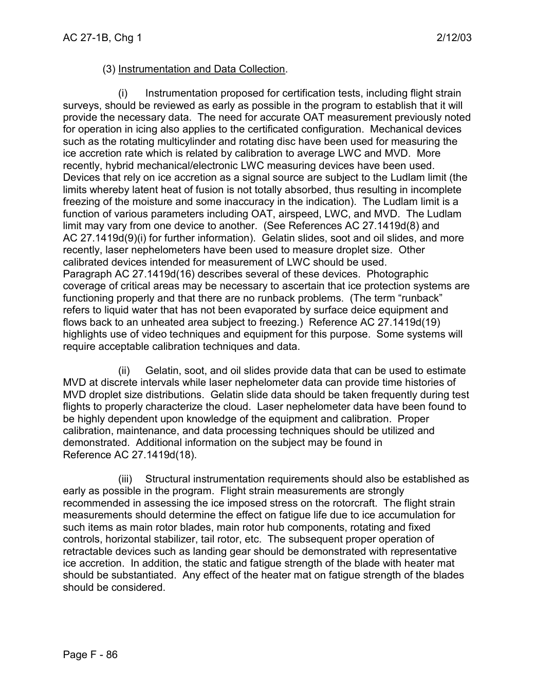
         (3) Instrumentation and Data Collection.

                  (i)    Instrumentation proposed for certification tests, including flight strain
surveys, should be reviewed as early as possible in the program to establish that it will
provide the necessary data. The need for accurate OAT measurement previously noted
for operation in icing also applies to the certificated configuration. Mechanical devices
such as the rotating multicylinder and rotating disc have been used for measuring the
ice accretion rate which is related by calibration to average LWC and MVD. More
recently, hybrid mechanical/electronic LWC measuring devices have been used.
Devices that rely on ice accretion as a signal source are subject to the Ludlam limit (the
limits whereby latent heat of fusion is not totally absorbed, thus resulting in incomplete
freezing of the moisture and some inaccuracy in the indication). The Ludlam limit is a
function of various parameters including OAT, airspeed, LWC, and MVD. The Ludlam
limit may vary from one device to another. (See References AC 27.1419d(8) and
AC 27.1419d(9)(i) for further information). Gelatin slides, soot and oil slides, and more
recently, laser nephelometers have been used to measure droplet size. Other
calibrated devices intended for measurement of LWC should be used.
Paragraph AC 27.1419d(16) describes several of these devices. Photographic
coverage of critical areas may be necessary to ascertain that ice protection systems are
functioning properly and that there are no runback problems. (The term “runback”
refers to liquid water that has not been evaporated by surface deice equipment and
flows back to an unheated area subject to freezing.) Reference AC 27.1419d(19)
highlights use of video techniques and equipment for this purpose. Some systems will
require acceptable calibration techniques and data.

                   (ii)   Gelatin, soot, and oil slides provide data that can be used to estimate
MVD at discrete intervals while laser nephelometer data can provide time histories of
MVD droplet size distributions. Gelatin slide data should be taken frequently during test
flights to properly characterize the cloud. Laser nephelometer data have been found to
be highly dependent upon knowledge of the equipment and calibration. Proper
calibration, maintenance, and data processing techniques should be utilized and
demonstrated. Additional information on the subject may be found in
Reference AC 27.1419d(18).

                    (iii)   Structural instrumentation requirements should also be established as
early as possible in the program. Flight strain measurements are strongly
recommended in assessing the ice imposed stress on the rotorcraft. The flight strain
measurements should determine the effect on fatigue life due to ice accumulation for
such items as main rotor blades, main rotor hub components, rotating and fixed
controls, horizontal stabilizer, tail rotor, etc. The subsequent proper operation of
retractable devices such as landing gear should be demonstrated with representative
ice accretion. In addition, the static and fatigue strength of the blade with heater mat
should be substantiated. Any effect of the heater mat on fatigue strength of the blades
should be considered.


Page F - 86
Saved from the FAA on November 17, 2026. All original pages are retained. Engineering explanations are presented separately below.
Aerospace Consulting / Engineering perspective
Start with the certification basis and the function.
Identify the applicable amendment before selecting the safety guidance. Connect intended functions and operating conditions to failure conditions, architecture decisions, common-cause considerations, verification and limitations. For flight controls and IFR work, carry the relevant 27.672, 27.1329 and Appendix B assumptions into the system safety and compliance evidence.
1196 original pages. 0 pages have reviewed text reflows. Original-first pages retain the source layout, with extracted text available for finding words.
A focused review, an agreed assessment package or ongoing support alongside your team. We can agree the relevant inputs and scope in the initial conversation.
This opens your email application.
Start a conversation
Tell us about your programme, the system you are developing and the support you need.
We can agree a focused use-case review, a defined evidence package or ongoing programme support.
This opens your email application.
Specialist aerospace expertise
Aerospace Consulting is led by Hussein Khimji, an FAA Designated Engineering Representative in systems and equipment, with a focus on system safety, flight controls and avionics.
We work with aircraft developers and systems suppliers to connect technical decisions, safety assessments and certification evidence.
This is the proposed introduction. The full About page will add your approved biography and associate expertise.
Systems engineering & development assurance
Tell us about the aircraft or system, its intended function, stage of development and the support you need.