Certification of Normal Category Rotorcraft — Changes 1–9
Normal category rotorcraft guidance with Changes 1–9 incorporated. Search the complete AC or start with the system safety, flight controls and instrument-flight guidance.
This source includes guidance for different amendments of Part 27. Match the guidance to the aircraft’s agreed certification basis: the 27.1309 entries for Amendments 27-21, 27-46 and 27-51 are separate. The base AC was issued on 30 September 1999; Change 9 is dated 23 June 2023. The FAA catalogue’s 30 September 2008 date is not the date of the latest change.
The source, within reach.
Search within this AC, jump to a source page, or download the complete saved publication.
This extraction supports search. Read the original page for complete notation and layout.
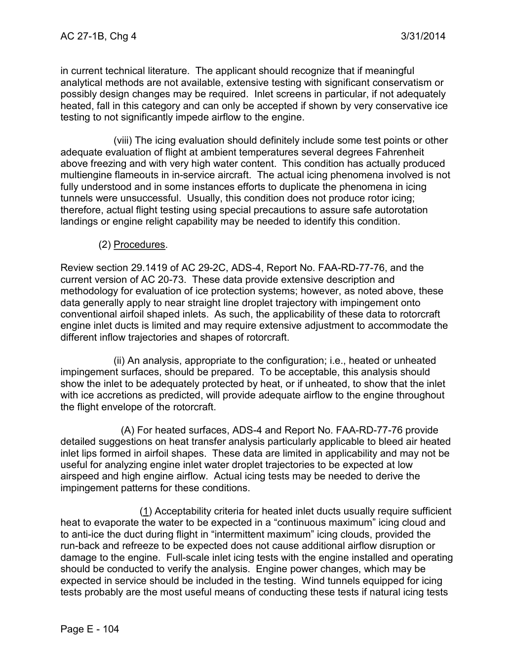
AC 27-1B, Chg 4                                                     3/31/2014


in current technical literature. The applicant should recognize that if meaningful
analytical methods are not available, extensive testing with significant conservatism or
possibly design changes may be required. Inlet screens in particular, if not adequately
heated, fall in this category and can only be accepted if shown by very conservative ice
testing to not significantly impede airflow to the engine.

                 (viii) The icing evaluation should definitely include some test points or other
adequate evaluation of flight at ambient temperatures several degrees Fahrenheit
above freezing and with very high water content. This condition has actually produced
multiengine flameouts in in-service aircraft. The actual icing phenomena involved is not
fully understood and in some instances efforts to duplicate the phenomena in icing
tunnels were unsuccessful. Usually, this condition does not produce rotor icing;
therefore, actual flight testing using special precautions to assure safe autorotation
landings or engine relight capability may be needed to identify this condition.

         (2) Procedures.

Review section 29.1419 of AC 29-2C, ADS-4, Report No. FAA-RD-77-76, and the
current version of AC 20-73. These data provide extensive description and
methodology for evaluation of ice protection systems; however, as noted above, these
data generally apply to near straight line droplet trajectory with impingement onto
conventional airfoil shaped inlets. As such, the applicability of these data to rotorcraft
engine inlet ducts is limited and may require extensive adjustment to accommodate the
different inflow trajectories and shapes of rotorcraft.

                   (ii) An analysis, appropriate to the configuration; i.e., heated or unheated
impingement surfaces, should be prepared. To be acceptable, this analysis should
show the inlet to be adequately protected by heat, or if unheated, to show that the inlet
with ice accretions as predicted, will provide adequate airflow to the engine throughout
the flight envelope of the rotorcraft.

              (A) For heated surfaces, ADS-4 and Report No. FAA-RD-77-76 provide
detailed suggestions on heat transfer analysis particularly applicable to bleed air heated
inlet lips formed in airfoil shapes. These data are limited in applicability and may not be
useful for analyzing engine inlet water droplet trajectories to be expected at low
airspeed and high engine airflow. Actual icing tests may be needed to derive the
impingement patterns for these conditions.

                   (1) Acceptability criteria for heated inlet ducts usually require sufficient
heat to evaporate the water to be expected in a “continuous maximum” icing cloud and
to anti-ice the duct during flight in “intermittent maximum” icing clouds, provided the
run-back and refreeze to be expected does not cause additional airflow disruption or
damage to the engine. Full-scale inlet icing tests with the engine installed and operating
should be conducted to verify the analysis. Engine power changes, which may be
expected in service should be included in the testing. Wind tunnels equipped for icing
tests probably are the most useful means of conducting these tests if natural icing tests


Page E - 104
Saved from the FAA on November 17, 2026. All original pages are retained. Engineering explanations are presented separately below.
Aerospace Consulting / Engineering perspective
Start with the certification basis and the function.
Identify the applicable amendment before selecting the safety guidance. Connect intended functions and operating conditions to failure conditions, architecture decisions, common-cause considerations, verification and limitations. For flight controls and IFR work, carry the relevant 27.672, 27.1329 and Appendix B assumptions into the system safety and compliance evidence.
1196 original pages. 0 pages have reviewed text reflows. Original-first pages retain the source layout, with extracted text available for finding words.
A focused review, an agreed assessment package or ongoing support alongside your team. We can agree the relevant inputs and scope in the initial conversation.
This opens your email application.
Start a conversation
Tell us about your programme, the system you are developing and the support you need.
We can agree a focused use-case review, a defined evidence package or ongoing programme support.
This opens your email application.
Specialist aerospace expertise
Aerospace Consulting is led by Hussein Khimji, an FAA Designated Engineering Representative in systems and equipment, with a focus on system safety, flight controls and avionics.
We work with aircraft developers and systems suppliers to connect technical decisions, safety assessments and certification evidence.
This is the proposed introduction. The full About page will add your approved biography and associate expertise.
Systems engineering & development assurance
Tell us about the aircraft or system, its intended function, stage of development and the support you need.