Certification of Normal Category Rotorcraft — Changes 1–9
Normal category rotorcraft guidance with Changes 1–9 incorporated. Search the complete AC or start with the system safety, flight controls and instrument-flight guidance.
This source includes guidance for different amendments of Part 27. Match the guidance to the aircraft’s agreed certification basis: the 27.1309 entries for Amendments 27-21, 27-46 and 27-51 are separate. The base AC was issued on 30 September 1999; Change 9 is dated 23 June 2023. The FAA catalogue’s 30 September 2008 date is not the date of the latest change.
The source, within reach.
Search within this AC, jump to a source page, or download the complete saved publication.
This extraction supports search. Read the original page for complete notation and layout.
AC 27-1B 9/30/99
the engine measured gas temperature does not correspond to that which would have
occurred on a minimum specification engine at hot day conditions.
(2) The correction factor would not apply to those components not affected by
changes in measured gas temperature (MGT) at a constant power. Typical items
expected to be affected by changes in the MGT at constant power would be engine oil
temperature, thermocouple harnesses, or other fluid, component, or ambient
temperatures in the vicinity of the engine hot-section or exhaust gases. Other items
remote from the hot-section, perhaps the starter-generator or fuel control, would not be
expected to be influenced by MGT variations; however, the items affected and the
magnitude of the factor to be applied should be established by testing.
(3) There are several acceptable methods for establishing the appropriate
thermal limit correction factor during development testing. The general idea is to
establish a stabilized flight condition, typically ground-run or IGE hover, and to vary the
measured gas temperature at approximately fixed power and OAT conditions. This may
be accomplished by utilizing engine anti-ice bleed air, customer bleed air, or by
ingesting warmer than ambient air (either an external source or the engine bleed air)
into the engine inlet. Care should be used in ingesting warmer than ambient air to
ensure that the warm air is diffused in order to avoid possible engine surge.
(i) If it is not possible to attain a suitable variation in MGT by these
methods, an acceptable, but more conservative, thermal limit correction may be
obtained by allowing both shaft horsepower and MGT to vary at a stabilized flight
condition and OAT.
(ii) The component temperature is plotted as a function of MGT, and the
thermal limit correction from any test day MGT for any flight condition, to the MGT that
would have existed with minimum specification engines on a hot day, is then applied to
derive the final measured component temperature.
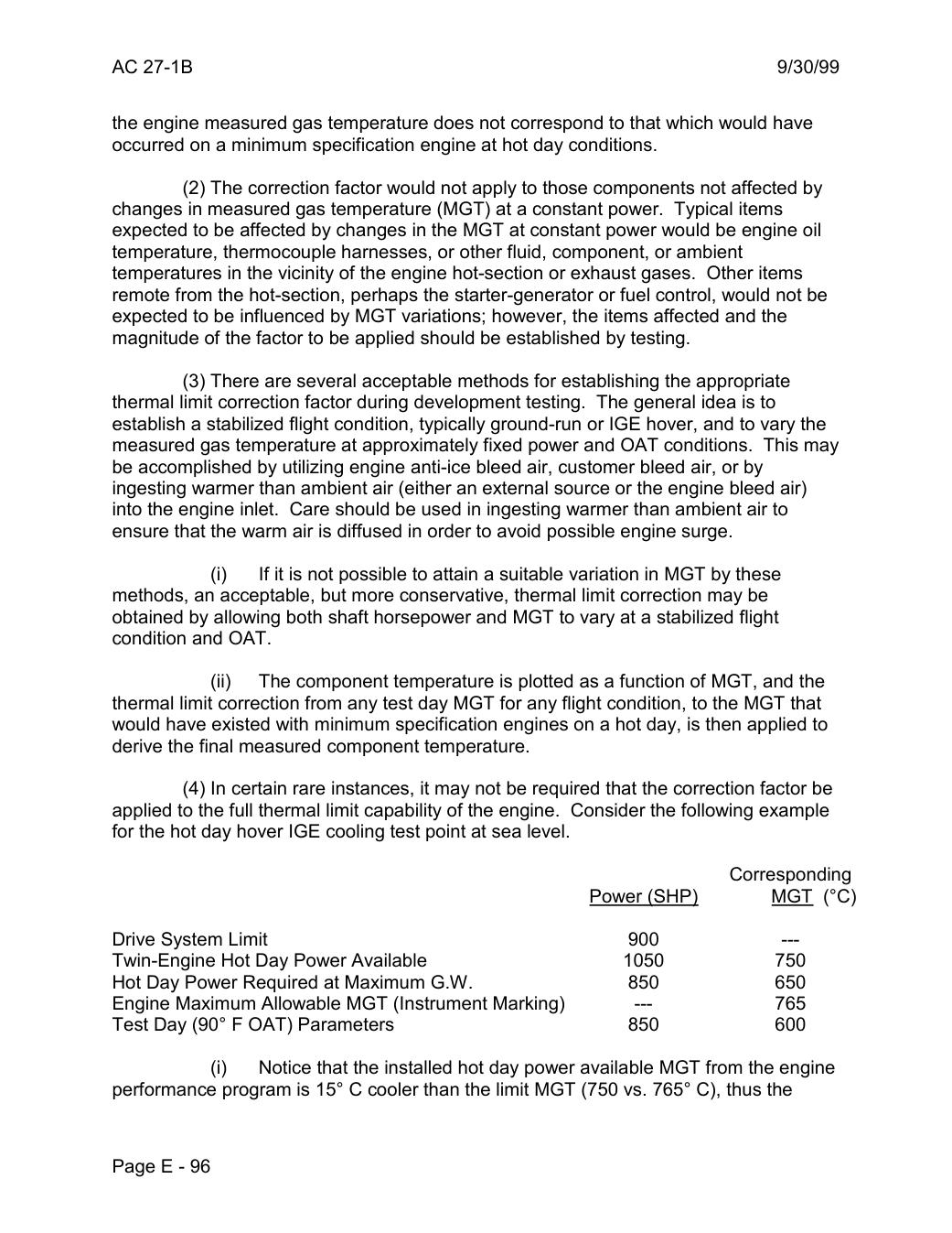
(4) In certain rare instances, it may not be required that the correction factor be
applied to the full thermal limit capability of the engine. Consider the following example
for the hot day hover IGE cooling test point at sea level.
Corresponding
Power (SHP) MGT (°C)
Drive System Limit 900 --
Twin-Engine Hot Day Power Available 1050 750
Hot Day Power Required at Maximum G.W. 850 650
Engine Maximum Allowable MGT (Instrument Marking) --- 765
Test Day (90° F OAT) Parameters 850 600
(i) Notice that the installed hot day power available MGT from the engine
performance program is 15° C cooler than the limit MGT (750 vs. 765° C), thus the
Page E - 96
Saved from the FAA on November 17, 2026. All original pages are retained. Engineering explanations are presented separately below.
Aerospace Consulting / Engineering perspective
Start with the certification basis and the function.
Identify the applicable amendment before selecting the safety guidance. Connect intended functions and operating conditions to failure conditions, architecture decisions, common-cause considerations, verification and limitations. For flight controls and IFR work, carry the relevant 27.672, 27.1329 and Appendix B assumptions into the system safety and compliance evidence.
1196 original pages. 0 pages have reviewed text reflows. Original-first pages retain the source layout, with extracted text available for finding words.
A focused review, an agreed assessment package or ongoing support alongside your team. We can agree the relevant inputs and scope in the initial conversation.
This opens your email application.
Start a conversation
Tell us about your programme, the system you are developing and the support you need.
We can agree a focused use-case review, a defined evidence package or ongoing programme support.
This opens your email application.
Specialist aerospace expertise
Aerospace Consulting is led by Hussein Khimji, an FAA Designated Engineering Representative in systems and equipment, with a focus on system safety, flight controls and avionics.
We work with aircraft developers and systems suppliers to connect technical decisions, safety assessments and certification evidence.
This is the proposed introduction. The full About page will add your approved biography and associate expertise.
Systems engineering & development assurance
Tell us about the aircraft or system, its intended function, stage of development and the support you need.