Certification of Normal Category Rotorcraft — Changes 1–9
Normal category rotorcraft guidance with Changes 1–9 incorporated. Search the complete AC or start with the system safety, flight controls and instrument-flight guidance.
This source includes guidance for different amendments of Part 27. Match the guidance to the aircraft’s agreed certification basis: the 27.1309 entries for Amendments 27-21, 27-46 and 27-51 are separate. The base AC was issued on 30 September 1999; Change 9 is dated 23 June 2023. The FAA catalogue’s 30 September 2008 date is not the date of the latest change.
The source, within reach.
Search within this AC, jump to a source page, or download the complete saved publication.
This extraction supports search. Read the original page for complete notation and layout.
9/30/99                                             AC 27-1B

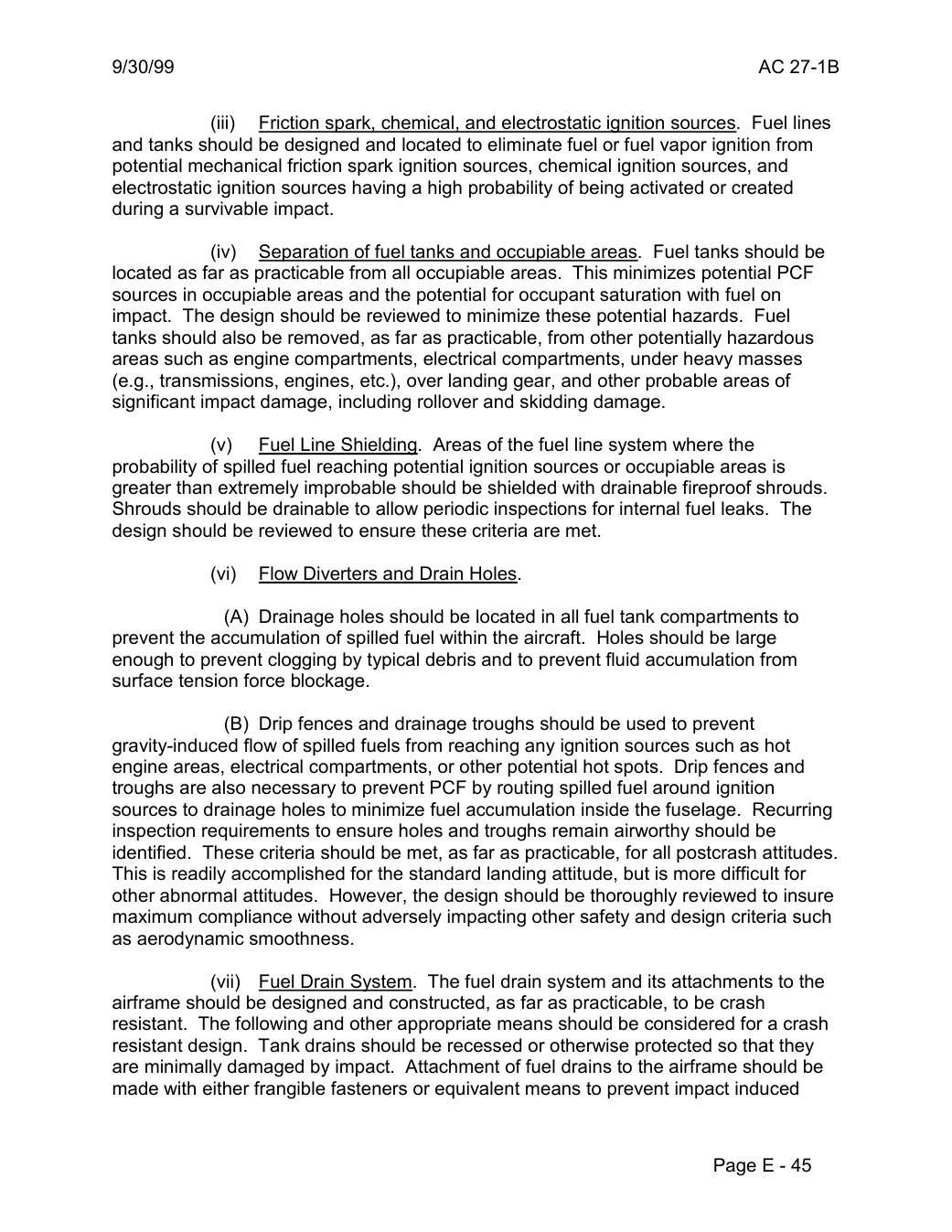
                    (iii)   Friction spark, chemical, and electrostatic ignition sources. Fuel lines
and tanks should be designed and located to eliminate fuel or fuel vapor ignition from
potential mechanical friction spark ignition sources, chemical ignition sources, and
electrostatic ignition sources having a high probability of being activated or created
during a survivable impact.

               (iv)  Separation of fuel tanks and occupiable areas. Fuel tanks should be
located as far as practicable from all occupiable areas. This minimizes potential PCF
sources in occupiable areas and the potential for occupant saturation with fuel on
impact. The design should be reviewed to minimize these potential hazards. Fuel
tanks should also be removed, as far as practicable, from other potentially hazardous
areas such as engine compartments, electrical compartments, under heavy masses
(e.g., transmissions, engines, etc.), over landing gear, and other probable areas of
significant impact damage, including rollover and skidding damage.

              (v)   Fuel Line Shielding. Areas of the fuel line system where the
probability of spilled fuel reaching potential ignition sources or occupiable areas is
greater than extremely improbable should be shielded with drainable fireproof shrouds.
Shrouds should be drainable to allow periodic inspections for internal fuel leaks. The
design should be reviewed to ensure these criteria are met.

               (vi)  Flow Diverters and Drain Holes.

              (A) Drainage holes should be located in all fuel tank compartments to
prevent the accumulation of spilled fuel within the aircraft. Holes should be large
enough to prevent clogging by typical debris and to prevent fluid accumulation from
surface tension force blockage.

              (B) Drip fences and drainage troughs should be used to prevent
gravity-induced flow of spilled fuels from reaching any ignition sources such as hot
engine areas, electrical compartments, or other potential hot spots. Drip fences and
troughs are also necessary to prevent PCF by routing spilled fuel around ignition
sources to drainage holes to minimize fuel accumulation inside the fuselage. Recurring
inspection requirements to ensure holes and troughs remain airworthy should be
identified. These criteria should be met, as far as practicable, for all postcrash attitudes.
This is readily accomplished for the standard landing attitude, but is more difficult for
other abnormal attitudes. However, the design should be thoroughly reviewed to insure
maximum compliance without adversely impacting other safety and design criteria such
as aerodynamic smoothness.

                (vii)  Fuel Drain System. The fuel drain system and its attachments to the
airframe should be designed and constructed, as far as practicable, to be crash
resistant. The following and other appropriate means should be considered for a crash
resistant design. Tank drains should be recessed or otherwise protected so that they
are minimally damaged by impact. Attachment of fuel drains to the airframe should be
made with either frangible fasteners or equivalent means to prevent impact induced


                                                       Page E - 45
Saved from the FAA on November 17, 2026. All original pages are retained. Engineering explanations are presented separately below.
Aerospace Consulting / Engineering perspective
Start with the certification basis and the function.
Identify the applicable amendment before selecting the safety guidance. Connect intended functions and operating conditions to failure conditions, architecture decisions, common-cause considerations, verification and limitations. For flight controls and IFR work, carry the relevant 27.672, 27.1329 and Appendix B assumptions into the system safety and compliance evidence.
1196 original pages. 0 pages have reviewed text reflows. Original-first pages retain the source layout, with extracted text available for finding words.
A focused review, an agreed assessment package or ongoing support alongside your team. We can agree the relevant inputs and scope in the initial conversation.
This opens your email application.
Start a conversation
Tell us about your programme, the system you are developing and the support you need.
We can agree a focused use-case review, a defined evidence package or ongoing programme support.
This opens your email application.
Specialist aerospace expertise
Aerospace Consulting is led by Hussein Khimji, an FAA Designated Engineering Representative in systems and equipment, with a focus on system safety, flight controls and avionics.
We work with aircraft developers and systems suppliers to connect technical decisions, safety assessments and certification evidence.
This is the proposed introduction. The full About page will add your approved biography and associate expertise.
Systems engineering & development assurance
Tell us about the aircraft or system, its intended function, stage of development and the support you need.