Certification of Normal Category Rotorcraft — Changes 1–9
Normal category rotorcraft guidance with Changes 1–9 incorporated. Search the complete AC or start with the system safety, flight controls and instrument-flight guidance.
This source includes guidance for different amendments of Part 27. Match the guidance to the aircraft’s agreed certification basis: the 27.1309 entries for Amendments 27-21, 27-46 and 27-51 are separate. The base AC was issued on 30 September 1999; Change 9 is dated 23 June 2023. The FAA catalogue’s 30 September 2008 date is not the date of the latest change.
The source, within reach.
Search within this AC, jump to a source page, or download the complete saved publication.
This extraction supports search. Read the original page for complete notation and layout.
AC 27-1B, Chg 1                                                           2/12/03


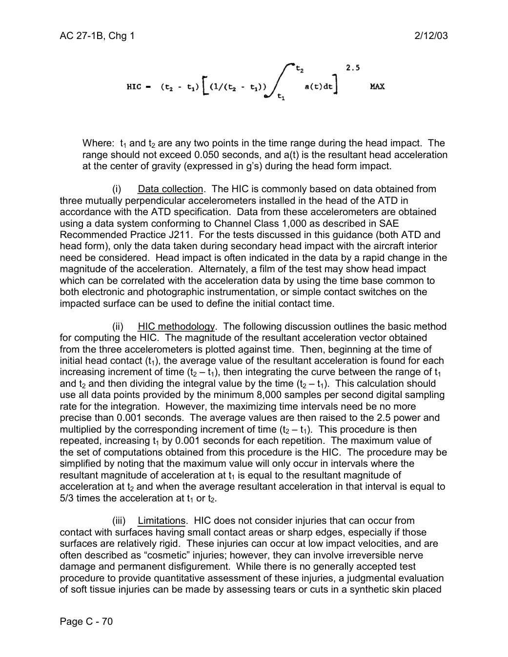
                                                                 2.5

                                                              MAX


    Where:  t1 and t2 are any two points in the time range during the head impact. The
    range should not exceed 0.050 seconds, and a(t) is the resultant head acceleration
     at the center of gravity (expressed in g’s) during the head form impact.

                  (i)   Data collection. The HIC is commonly based on data obtained from
three mutually perpendicular accelerometers installed in the head of the ATD in
accordance with the ATD specification. Data from these accelerometers are obtained
using a data system conforming to Channel Class 1,000 as described in SAE
Recommended Practice J211. For the tests discussed in this guidance (both ATD and
head form), only the data taken during secondary head impact with the aircraft interior
need be considered. Head impact is often indicated in the data by a rapid change in the
magnitude of the acceleration. Alternately, a film of the test may show head impact
which can be correlated with the acceleration data by using the time base common to
both electronic and photographic instrumentation, or simple contact switches on the
impacted surface can be used to define the initial contact time.

                   (ii)   HIC methodology. The following discussion outlines the basic method
for computing the HIC. The magnitude of the resultant acceleration vector obtained
from the three accelerometers is plotted against time. Then, beginning at the time of
initial head contact (t1), the average value of the resultant acceleration is found for each
increasing increment of time (t2 – t1), then integrating the curve between the range of t1
and t2 and then dividing the integral value by the time (t2 – t1). This calculation should
use all data points provided by the minimum 8,000 samples per second digital sampling
rate for the integration. However, the maximizing time intervals need be no more
precise than 0.001 seconds. The average values are then raised to the 2.5 power and
multiplied by the corresponding increment of time (t2 – t1). This procedure is then
repeated, increasing t1 by 0.001 seconds for each repetition. The maximum value of
the set of computations obtained from this procedure is the HIC. The procedure may be
simplified by noting that the maximum value will only occur in intervals where the
resultant magnitude of acceleration at t1 is equal to the resultant magnitude of
acceleration at t2 and when the average resultant acceleration in that interval is equal to
5/3 times the acceleration at t1 or t2.

                    (iii)   Limitations. HIC does not consider injuries that can occur from
contact with surfaces having small contact areas or sharp edges, especially if those
surfaces are relatively rigid. These injuries can occur at low impact velocities, and are
often described as “cosmetic” injuries; however, they can involve irreversible nerve
damage and permanent disfigurement. While there is no generally accepted test
procedure to provide quantitative assessment of these injuries, a judgmental evaluation
of soft tissue injuries can be made by assessing tears or cuts in a synthetic skin placed

Page C - 70
Saved from the FAA on November 17, 2026. All original pages are retained. Engineering explanations are presented separately below.
Aerospace Consulting / Engineering perspective
Start with the certification basis and the function.
Identify the applicable amendment before selecting the safety guidance. Connect intended functions and operating conditions to failure conditions, architecture decisions, common-cause considerations, verification and limitations. For flight controls and IFR work, carry the relevant 27.672, 27.1329 and Appendix B assumptions into the system safety and compliance evidence.
1196 original pages. 0 pages have reviewed text reflows. Original-first pages retain the source layout, with extracted text available for finding words.
A focused review, an agreed assessment package or ongoing support alongside your team. We can agree the relevant inputs and scope in the initial conversation.
This opens your email application.
Start a conversation
Tell us about your programme, the system you are developing and the support you need.
We can agree a focused use-case review, a defined evidence package or ongoing programme support.
This opens your email application.
Specialist aerospace expertise
Aerospace Consulting is led by Hussein Khimji, an FAA Designated Engineering Representative in systems and equipment, with a focus on system safety, flight controls and avionics.
We work with aircraft developers and systems suppliers to connect technical decisions, safety assessments and certification evidence.
This is the proposed introduction. The full About page will add your approved biography and associate expertise.
Systems engineering & development assurance
Tell us about the aircraft or system, its intended function, stage of development and the support you need.