Certification of Normal Category Rotorcraft — Changes 1–9
Normal category rotorcraft guidance with Changes 1–9 incorporated. Search the complete AC or start with the system safety, flight controls and instrument-flight guidance.
This source includes guidance for different amendments of Part 27. Match the guidance to the aircraft’s agreed certification basis: the 27.1309 entries for Amendments 27-21, 27-46 and 27-51 are separate. The base AC was issued on 30 September 1999; Change 9 is dated 23 June 2023. The FAA catalogue’s 30 September 2008 date is not the date of the latest change.
The source, within reach.
Search within this AC, jump to a source page, or download the complete saved publication.
This extraction supports search. Read the original page for complete notation and layout.
AC 27-1B, Chg 7                                                                       2/4/2016


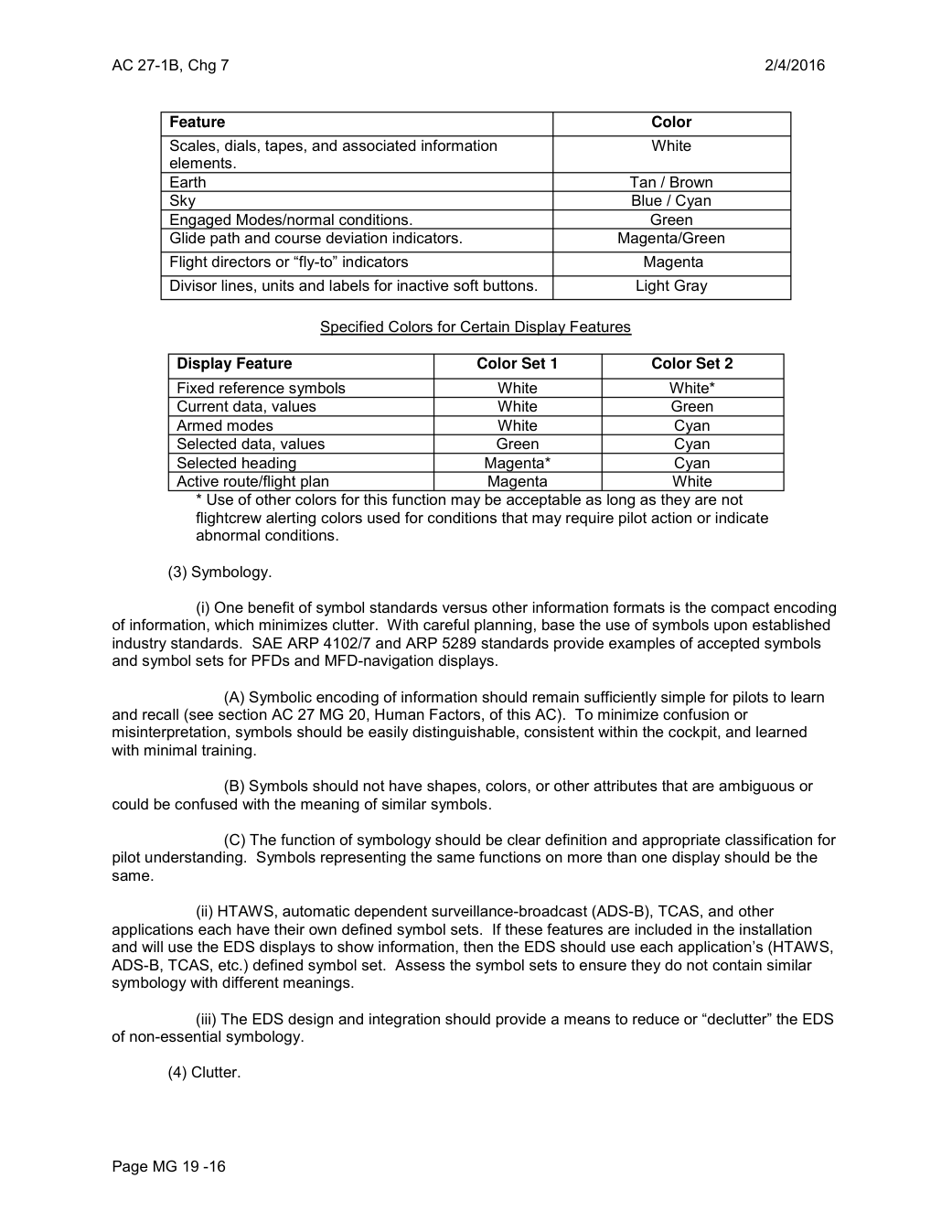
       Feature                                                     Color
        Scales, dials, tapes, and associated information                   White
        elements.
        Earth                                               Tan / Brown
       Sky                                                        Blue / Cyan
      Engaged Modes/normal conditions.                           Green
        Glide path and course deviation indicators.                   Magenta/Green
         Flight directors or “fly-to” indicators                           Magenta
         Divisor lines, units and labels for inactive soft buttons.               Light Gray

                             Specified Colors for Certain Display Features

        Display Feature                       Color Set 1           Color Set 2
         Fixed reference symbols                   White                 White*
         Current data, values                       White               Green
       Armed modes                            White               Cyan
         Selected data, values                    Green               Cyan
         Selected heading                       Magenta*              Cyan
         Active route/flight plan                  Magenta                White
              * Use of other colors for this function may be acceptable as long as they are not
             flightcrew alerting colors used for conditions that may require pilot action or indicate
          abnormal conditions.

         (3) Symbology.

                  (i) One benefit of symbol standards versus other information formats is the compact encoding
of information, which minimizes clutter. With careful planning, base the use of symbols upon established
industry standards. SAE ARP 4102/7 and ARP 5289 standards provide examples of accepted symbols
and symbol sets for PFDs and MFD-navigation displays.

                (A) Symbolic encoding of information should remain sufficiently simple for pilots to learn
and recall (see section AC 27 MG 20, Human Factors, of this AC). To minimize confusion or
misinterpretation, symbols should be easily distinguishable, consistent within the cockpit, and learned
with minimal training.

                (B) Symbols should not have shapes, colors, or other attributes that are ambiguous or
could be confused with the meaning of similar symbols.

                (C) The function of symbology should be clear definition and appropriate classification for
pilot understanding. Symbols representing the same functions on more than one display should be the
same.

                    (ii) HTAWS, automatic dependent surveillance-broadcast (ADS-B), TCAS, and other
applications each have their own defined symbol sets.  If these features are included in the installation
and will use the EDS displays to show information, then the EDS should use each application’s (HTAWS,
ADS-B, TCAS, etc.) defined symbol set. Assess the symbol sets to ensure they do not contain similar
symbology with different meanings.

                     (iii) The EDS design and integration should provide a means to reduce or “declutter” the EDS
of non-essential symbology.

         (4) Clutter.


Page MG 19 -16
Saved from the FAA on November 17, 2026. All original pages are retained. Engineering explanations are presented separately below.
Aerospace Consulting / Engineering perspective
Start with the certification basis and the function.
Identify the applicable amendment before selecting the safety guidance. Connect intended functions and operating conditions to failure conditions, architecture decisions, common-cause considerations, verification and limitations. For flight controls and IFR work, carry the relevant 27.672, 27.1329 and Appendix B assumptions into the system safety and compliance evidence.
1196 original pages. 0 pages have reviewed text reflows. Original-first pages retain the source layout, with extracted text available for finding words.
A focused review, an agreed assessment package or ongoing support alongside your team. We can agree the relevant inputs and scope in the initial conversation.
This opens your email application.
Start a conversation
Tell us about your programme, the system you are developing and the support you need.
We can agree a focused use-case review, a defined evidence package or ongoing programme support.
This opens your email application.
Specialist aerospace expertise
Aerospace Consulting is led by Hussein Khimji, an FAA Designated Engineering Representative in systems and equipment, with a focus on system safety, flight controls and avionics.
We work with aircraft developers and systems suppliers to connect technical decisions, safety assessments and certification evidence.
This is the proposed introduction. The full About page will add your approved biography and associate expertise.
Systems engineering & development assurance
Tell us about the aircraft or system, its intended function, stage of development and the support you need.