Certification of Normal Category Rotorcraft — Changes 1–9
Normal category rotorcraft guidance with Changes 1–9 incorporated. Search the complete AC or start with the system safety, flight controls and instrument-flight guidance.
This source includes guidance for different amendments of Part 27. Match the guidance to the aircraft’s agreed certification basis: the 27.1309 entries for Amendments 27-21, 27-46 and 27-51 are separate. The base AC was issued on 30 September 1999; Change 9 is dated 23 June 2023. The FAA catalogue’s 30 September 2008 date is not the date of the latest change.
The source, within reach.
Search within this AC, jump to a source page, or download the complete saved publication.
This extraction supports search. Read the original page for complete notation and layout.
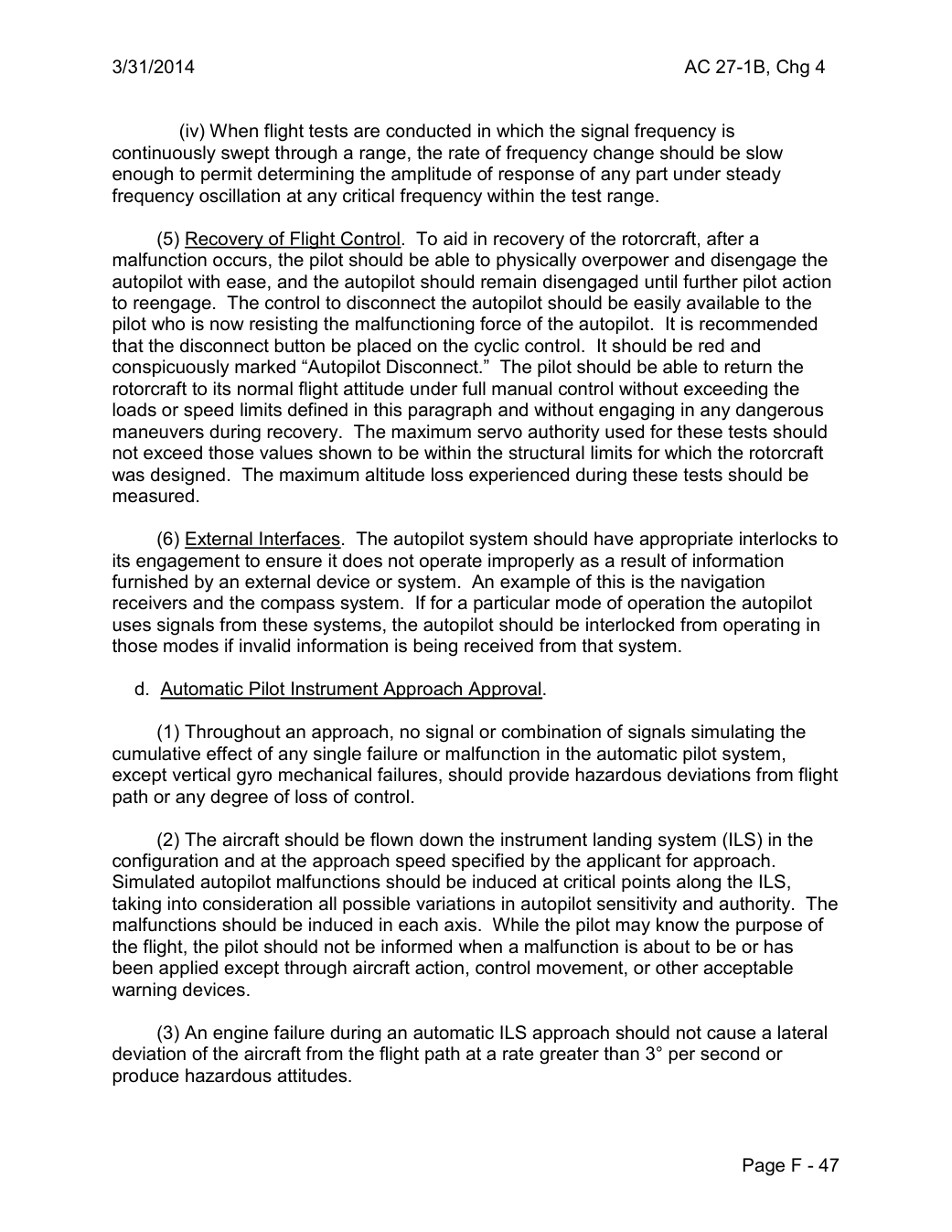
3/31/2014                                      AC 27-1B, Chg 4


          (iv) When flight tests are conducted in which the signal frequency is
continuously swept through a range, the rate of frequency change should be slow
enough to permit determining the amplitude of response of any part under steady
frequency oscillation at any critical frequency within the test range.

      (5) Recovery of Flight Control. To aid in recovery of the rotorcraft, after a
malfunction occurs, the pilot should be able to physically overpower and disengage the
autopilot with ease, and the autopilot should remain disengaged until further pilot action
to reengage. The control to disconnect the autopilot should be easily available to the
pilot who is now resisting the malfunctioning force of the autopilot.  It is recommended
that the disconnect button be placed on the cyclic control.  It should be red and
conspicuously marked “Autopilot Disconnect.” The pilot should be able to return the
rotorcraft to its normal flight attitude under full manual control without exceeding the
loads or speed limits defined in this paragraph and without engaging in any dangerous
maneuvers during recovery. The maximum servo authority used for these tests should
not exceed those values shown to be within the structural limits for which the rotorcraft
was designed. The maximum altitude loss experienced during these tests should be
measured.

      (6) External Interfaces. The autopilot system should have appropriate interlocks to
its engagement to ensure it does not operate improperly as a result of information
furnished by an external device or system. An example of this is the navigation
receivers and the compass system.  If for a particular mode of operation the autopilot
uses signals from these systems, the autopilot should be interlocked from operating in
those modes if invalid information is being received from that system.

   d. Automatic Pilot Instrument Approach Approval.

      (1) Throughout an approach, no signal or combination of signals simulating the
cumulative effect of any single failure or malfunction in the automatic pilot system,
except vertical gyro mechanical failures, should provide hazardous deviations from flight
path or any degree of loss of control.

      (2) The aircraft should be flown down the instrument landing system (ILS) in the
configuration and at the approach speed specified by the applicant for approach.
Simulated autopilot malfunctions should be induced at critical points along the ILS,
taking into consideration all possible variations in autopilot sensitivity and authority. The
malfunctions should be induced in each axis. While the pilot may know the purpose of
the flight, the pilot should not be informed when a malfunction is about to be or has
been applied except through aircraft action, control movement, or other acceptable
warning devices.

      (3) An engine failure during an automatic ILS approach should not cause a lateral
deviation of the aircraft from the flight path at a rate greater than 3° per second or
produce hazardous attitudes.


                                                          Page F - 47
Saved from the FAA on November 17, 2026. All original pages are retained. Engineering explanations are presented separately below.
Aerospace Consulting / Engineering perspective
Start with the certification basis and the function.
Identify the applicable amendment before selecting the safety guidance. Connect intended functions and operating conditions to failure conditions, architecture decisions, common-cause considerations, verification and limitations. For flight controls and IFR work, carry the relevant 27.672, 27.1329 and Appendix B assumptions into the system safety and compliance evidence.
1196 original pages. 0 pages have reviewed text reflows. Original-first pages retain the source layout, with extracted text available for finding words.
A focused review, an agreed assessment package or ongoing support alongside your team. We can agree the relevant inputs and scope in the initial conversation.
This opens your email application.
Start a conversation
Tell us about your programme, the system you are developing and the support you need.
We can agree a focused use-case review, a defined evidence package or ongoing programme support.
This opens your email application.
Specialist aerospace expertise
Aerospace Consulting is led by Hussein Khimji, an FAA Designated Engineering Representative in systems and equipment, with a focus on system safety, flight controls and avionics.
We work with aircraft developers and systems suppliers to connect technical decisions, safety assessments and certification evidence.
This is the proposed introduction. The full About page will add your approved biography and associate expertise.
Systems engineering & development assurance
Tell us about the aircraft or system, its intended function, stage of development and the support you need.