Certification of Normal Category Rotorcraft — Changes 1–9
Normal category rotorcraft guidance with Changes 1–9 incorporated. Search the complete AC or start with the system safety, flight controls and instrument-flight guidance.
This source includes guidance for different amendments of Part 27. Match the guidance to the aircraft’s agreed certification basis: the 27.1309 entries for Amendments 27-21, 27-46 and 27-51 are separate. The base AC was issued on 30 September 1999; Change 9 is dated 23 June 2023. The FAA catalogue’s 30 September 2008 date is not the date of the latest change.
The source, within reach.
Search within this AC, jump to a source page, or download the complete saved publication.
This extraction supports search. Read the original page for complete notation and layout.
2/4/2016                                      AC 27-1B, Chg 7


AC 27.1321.   § 27.1321 (Amendment 27-13) ARRANGEMENT AND VISIBILITY.

    a. Background. Part 27 contains specific requirements for locating instruments to
allow pilots to operate the rotorcraft safely within authorized limits and to indicate
system conditions. The instruments should be arranged for use by any pilot and must
be readily visible to the pilot. The design for the instrument location and arrangement,
with respect to the pilot’s seat, should accommodate 5th to the 95th percentile of male
and female pilots. Pilots within this height range should be able to see and, where
necessary, reach and operate all of the displays.

    b. Procedures.

       (1) When evaluating the location of the instruments for rotorcraft approved for
VFR (IFR locations are discussed in section AC 27 Appendix B of this AC), the
placement of flight, navigation, and powerplant instruments should be such that the
pilot(s) can easily see and read the instruments when seated normally. Additionally, the
instruments’ location should minimize unnecessary pilot head turning.

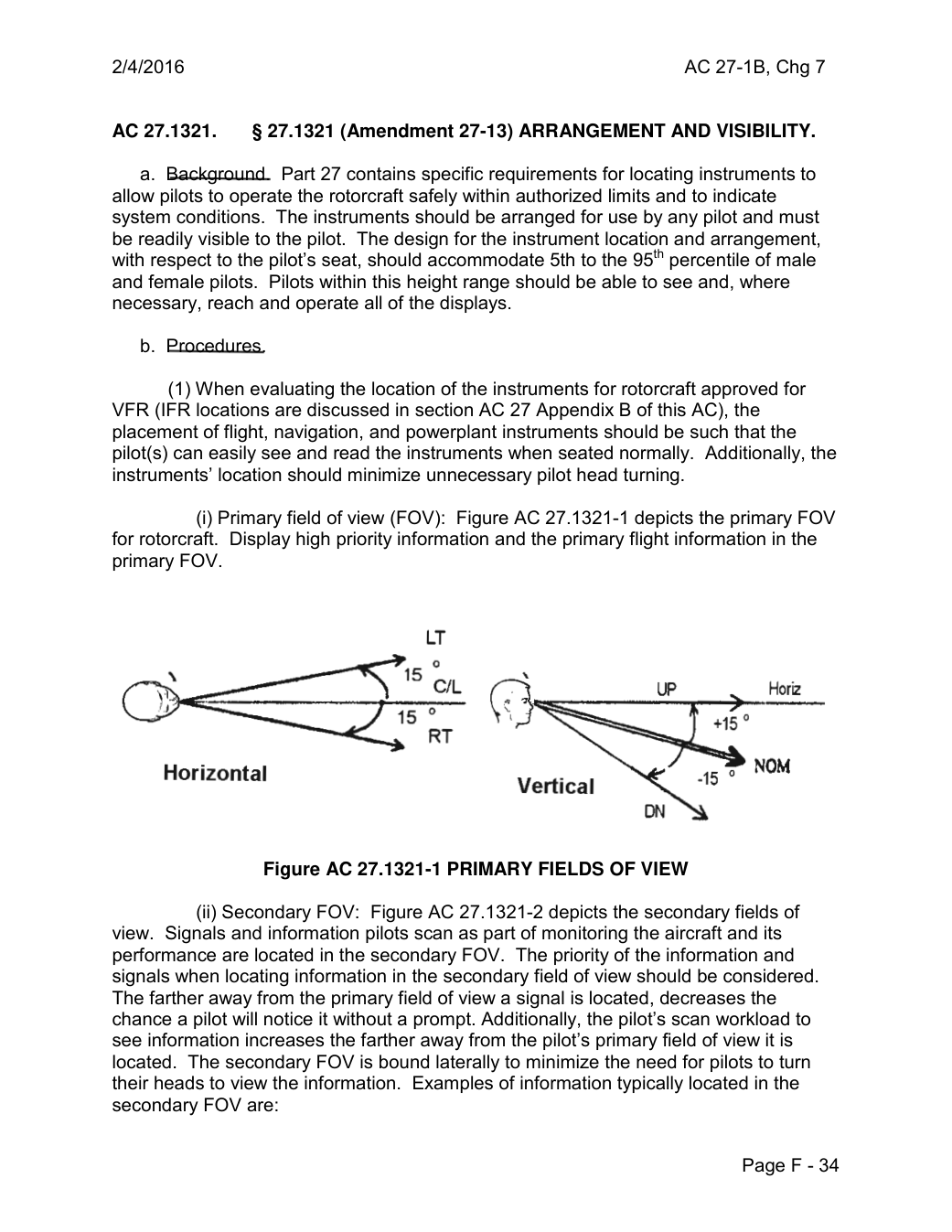
               (i) Primary field of view (FOV): Figure AC 27.1321-1 depicts the primary FOV
for rotorcraft. Display high priority information and the primary flight information in the
primary FOV.


                                LT

                                                             0
                                15 C/L                                                        UP               Horiz
                                                            0
                          RT
                                                                                                                           0  NOM     Horizontal                                                               -15                                           Vertical


                Figure AC 27.1321-1 PRIMARY FIELDS OF VIEW

                (ii) Secondary FOV: Figure AC 27.1321-2 depicts the secondary fields of
view. Signals and information pilots scan as part of monitoring the aircraft and its
performance are located in the secondary FOV. The priority of the information and
signals when locating information in the secondary field of view should be considered.
The farther away from the primary field of view a signal is located, decreases the
chance a pilot will notice it without a prompt. Additionally, the pilot’s scan workload to
see information increases the farther away from the pilot’s primary field of view it is
located. The secondary FOV is bound laterally to minimize the need for pilots to turn
their heads to view the information. Examples of information typically located in the
secondary FOV are:

                                                          Page F - 34
Saved from the FAA on November 17, 2026. All original pages are retained. Engineering explanations are presented separately below.
Aerospace Consulting / Engineering perspective
Start with the certification basis and the function.
Identify the applicable amendment before selecting the safety guidance. Connect intended functions and operating conditions to failure conditions, architecture decisions, common-cause considerations, verification and limitations. For flight controls and IFR work, carry the relevant 27.672, 27.1329 and Appendix B assumptions into the system safety and compliance evidence.
1196 original pages. 0 pages have reviewed text reflows. Original-first pages retain the source layout, with extracted text available for finding words.
A focused review, an agreed assessment package or ongoing support alongside your team. We can agree the relevant inputs and scope in the initial conversation.
This opens your email application.
Start a conversation
Tell us about your programme, the system you are developing and the support you need.
We can agree a focused use-case review, a defined evidence package or ongoing programme support.
This opens your email application.
Specialist aerospace expertise
Aerospace Consulting is led by Hussein Khimji, an FAA Designated Engineering Representative in systems and equipment, with a focus on system safety, flight controls and avionics.
We work with aircraft developers and systems suppliers to connect technical decisions, safety assessments and certification evidence.
This is the proposed introduction. The full About page will add your approved biography and associate expertise.
Systems engineering & development assurance
Tell us about the aircraft or system, its intended function, stage of development and the support you need.