Certification of Normal Category Rotorcraft — Changes 1–9
Normal category rotorcraft guidance with Changes 1–9 incorporated. Search the complete AC or start with the system safety, flight controls and instrument-flight guidance.
This source includes guidance for different amendments of Part 27. Match the guidance to the aircraft’s agreed certification basis: the 27.1309 entries for Amendments 27-21, 27-46 and 27-51 are separate. The base AC was issued on 30 September 1999; Change 9 is dated 23 June 2023. The FAA catalogue’s 30 September 2008 date is not the date of the latest change.
The source, within reach.
Search within this AC, jump to a source page, or download the complete saved publication.
This extraction supports search. Read the original page for complete notation and layout.
AC 27-1B, Chg 4                                                     3/31/2014


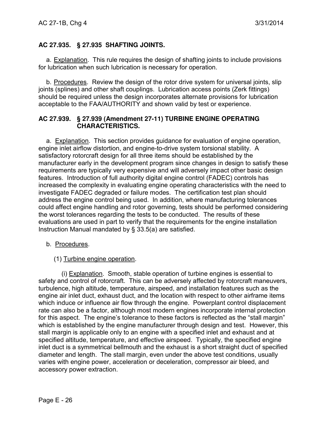
AC 27.935.  § 27.935 SHAFTING JOINTS.

   a. Explanation. This rule requires the design of shafting joints to include provisions
for lubrication when such lubrication is necessary for operation.

   b. Procedures. Review the design of the rotor drive system for universal joints, slip
joints (splines) and other shaft couplings. Lubrication access points (Zerk fittings)
should be required unless the design incorporates alternate provisions for lubrication
acceptable to the FAA/AUTHORITY and shown valid by test or experience.

AC 27.939.  § 27.939 (Amendment 27-11) TURBINE ENGINE OPERATING
          CHARACTERISTICS.

   a. Explanation. This section provides guidance for evaluation of engine operation,
engine inlet airflow distortion, and engine-to-drive system torsional stability. A
satisfactory rotorcraft design for all three items should be established by the
manufacturer early in the development program since changes in design to satisfy these
requirements are typically very expensive and will adversely impact other basic design
features. Introduction of full authority digital engine control (FADEC) controls has
increased the complexity in evaluating engine operating characteristics with the need to
investigate FADEC degraded or failure modes. The certification test plan should
address the engine control being used. In addition, where manufacturing tolerances
could affect engine handling and rotor governing, tests should be performed considering
the worst tolerances regarding the tests to be conducted. The results of these
evaluations are used in part to verify that the requirements for the engine installation
Instruction Manual mandated by § 33.5(a) are satisfied.

   b. Procedures.

      (1) Turbine engine operation.

            (i) Explanation. Smooth, stable operation of turbine engines is essential to
safety and control of rotorcraft. This can be adversely affected by rotorcraft maneuvers,
turbulence, high altitude, temperature, airspeed, and installation features such as the
engine air inlet duct, exhaust duct, and the location with respect to other airframe items
which induce or influence air flow through the engine. Powerplant control displacement
rate can also be a factor, although most modern engines incorporate internal protection
for this aspect. The engine’s tolerance to these factors is reflected as the “stall margin”
which is established by the engine manufacturer through design and test. However, this
stall margin is applicable only to an engine with a specified inlet and exhaust and at
specified altitude, temperature, and effective airspeed. Typically, the specified engine
inlet duct is a symmetrical bellmouth and the exhaust is a short straight duct of specified
diameter and length. The stall margin, even under the above test conditions, usually
varies with engine power, acceleration or deceleration, compressor air bleed, and
accessory power extraction.


Page E - 26
Saved from the FAA on November 17, 2026. All original pages are retained. Engineering explanations are presented separately below.
Aerospace Consulting / Engineering perspective
Start with the certification basis and the function.
Identify the applicable amendment before selecting the safety guidance. Connect intended functions and operating conditions to failure conditions, architecture decisions, common-cause considerations, verification and limitations. For flight controls and IFR work, carry the relevant 27.672, 27.1329 and Appendix B assumptions into the system safety and compliance evidence.
1196 original pages. 0 pages have reviewed text reflows. Original-first pages retain the source layout, with extracted text available for finding words.
A focused review, an agreed assessment package or ongoing support alongside your team. We can agree the relevant inputs and scope in the initial conversation.
This opens your email application.
Start a conversation
Tell us about your programme, the system you are developing and the support you need.
We can agree a focused use-case review, a defined evidence package or ongoing programme support.
This opens your email application.
Specialist aerospace expertise
Aerospace Consulting is led by Hussein Khimji, an FAA Designated Engineering Representative in systems and equipment, with a focus on system safety, flight controls and avionics.
We work with aircraft developers and systems suppliers to connect technical decisions, safety assessments and certification evidence.
This is the proposed introduction. The full About page will add your approved biography and associate expertise.
Systems engineering & development assurance
Tell us about the aircraft or system, its intended function, stage of development and the support you need.