Certification of Normal Category Rotorcraft — Changes 1–9
Normal category rotorcraft guidance with Changes 1–9 incorporated. Search the complete AC or start with the system safety, flight controls and instrument-flight guidance.
This source includes guidance for different amendments of Part 27. Match the guidance to the aircraft’s agreed certification basis: the 27.1309 entries for Amendments 27-21, 27-46 and 27-51 are separate. The base AC was issued on 30 September 1999; Change 9 is dated 23 June 2023. The FAA catalogue’s 30 September 2008 date is not the date of the latest change.
The source, within reach.
Search within this AC, jump to a source page, or download the complete saved publication.
This extraction supports search. Read the original page for complete notation and layout.
5/1/2014                                         AC 27.1B, Chg 7
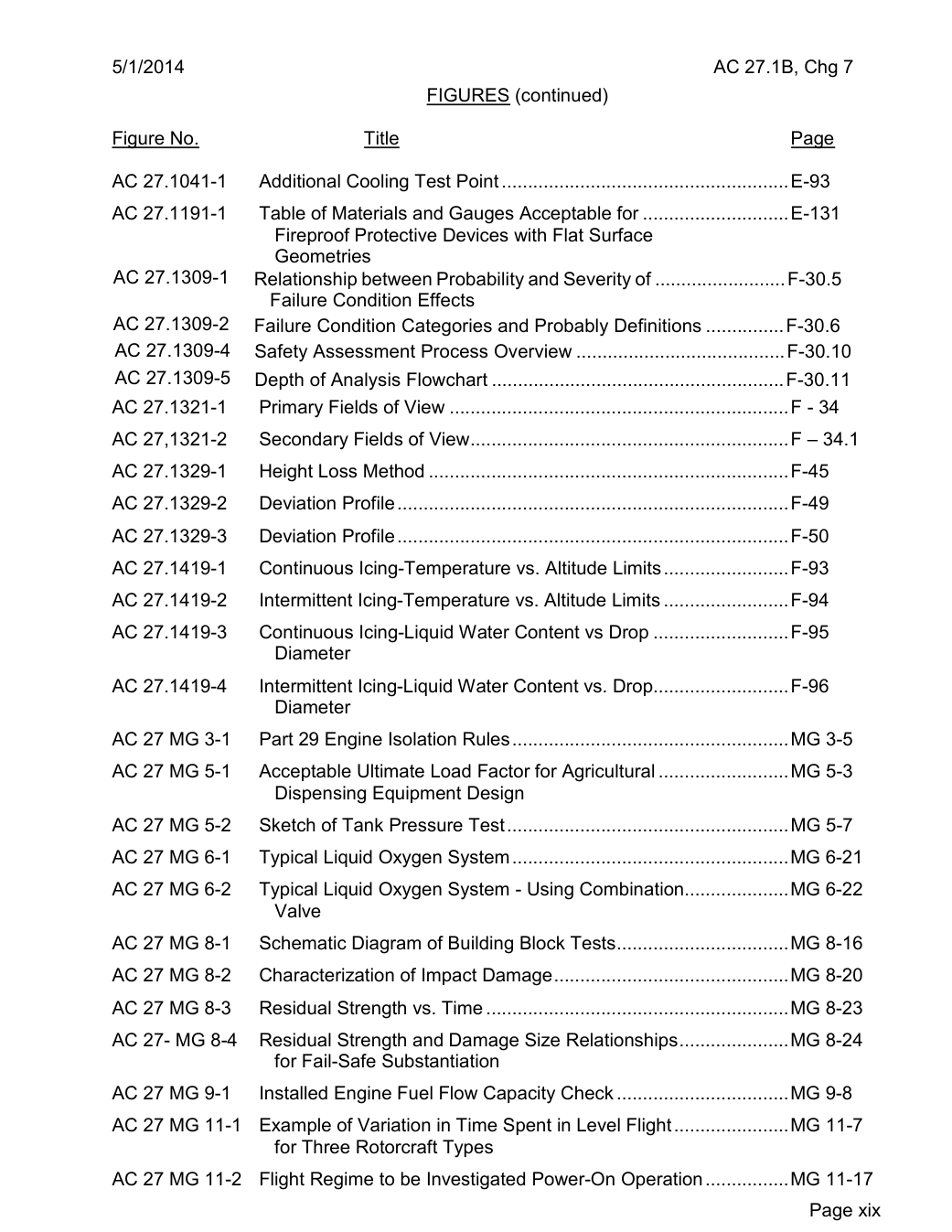
                           FIGURES (continued)

Figure No.                       Title                                    Page

AC 27.1041-1    Additional Cooling Test Point.......................................................E-93
AC 27.1191-1   Table of Materials and Gauges Acceptable for ............................E-131
                    Fireproof Protective Devices with Flat Surface
                 Geometries
AC 27.1309-1   Relationship between Probability and Severity of .........................F-30.5
                   Failure Condition Effects
AC 27.1309-2   Failure Condition Categories and Probably Definitions ...............F-30.6
AC 27.1309-4   Safety Assessment Process Overview ........................................F-30.10
AC 27.1309-5  Depth of Analysis Flowchart ........................................................F-30.11
AC 27.1321-1   Primary Fields of View .................................................................F - 34
AC 27,1321-2   Secondary Fields of View.............................................................F – 34.1
AC 27.1329-1    Height Loss Method .....................................................................F-45
AC 27.1329-2    Deviation Profile...........................................................................F-49
AC 27.1329-3    Deviation Profile...........................................................................F-50
AC 27.1419-1   Continuous Icing-Temperature vs. Altitude Limits........................F-93
AC 27.1419-2    Intermittent Icing-Temperature vs. Altitude Limits ........................F-94
AC 27.1419-3   Continuous Icing-Liquid Water Content vs Drop ..........................F-95
                 Diameter
AC 27.1419-4    Intermittent Icing-Liquid Water Content vs. Drop..........................F-96
                 Diameter
AC 27 MG 3-1   Part 29 Engine Isolation Rules.....................................................MG 3-5
AC 27 MG 5-1   Acceptable Ultimate Load Factor for Agricultural .........................MG 5-3
                  Dispensing Equipment Design
AC 27 MG 5-2   Sketch of Tank Pressure Test......................................................MG 5-7
AC 27 MG 6-1   Typical Liquid Oxygen System.....................................................MG 6-21
AC 27 MG 6-2   Typical Liquid Oxygen System - Using Combination....................MG 6-22
                 Valve
AC 27 MG 8-1   Schematic Diagram of Building Block Tests.................................MG 8-16
AC 27 MG 8-2   Characterization of Impact Damage.............................................MG 8-20
AC 27 MG 8-3   Residual Strength vs. Time ..........................................................MG 8-23
AC 27- MG 8-4  Residual Strength and Damage Size Relationships.....................MG 8-24
                      for Fail-Safe Substantiation
AC 27 MG 9-1    Installed Engine Fuel Flow Capacity Check.................................MG 9-8
AC 27 MG 11-1  Example of Variation in Time Spent in Level Flight......................MG 11-7
                      for Three Rotorcraft Types
AC 27 MG 11-2  Flight Regime to be Investigated Power-On Operation................MG 11-17
                                                                Page xix
Saved from the FAA on November 17, 2026. All original pages are retained. Engineering explanations are presented separately below.
Aerospace Consulting / Engineering perspective
Start with the certification basis and the function.
Identify the applicable amendment before selecting the safety guidance. Connect intended functions and operating conditions to failure conditions, architecture decisions, common-cause considerations, verification and limitations. For flight controls and IFR work, carry the relevant 27.672, 27.1329 and Appendix B assumptions into the system safety and compliance evidence.
1196 original pages. 0 pages have reviewed text reflows. Original-first pages retain the source layout, with extracted text available for finding words.
A focused review, an agreed assessment package or ongoing support alongside your team. We can agree the relevant inputs and scope in the initial conversation.
This opens your email application.
Start a conversation
Tell us about your programme, the system you are developing and the support you need.
We can agree a focused use-case review, a defined evidence package or ongoing programme support.
This opens your email application.
Specialist aerospace expertise
Aerospace Consulting is led by Hussein Khimji, an FAA Designated Engineering Representative in systems and equipment, with a focus on system safety, flight controls and avionics.
We work with aircraft developers and systems suppliers to connect technical decisions, safety assessments and certification evidence.
This is the proposed introduction. The full About page will add your approved biography and associate expertise.
Systems engineering & development assurance
Tell us about the aircraft or system, its intended function, stage of development and the support you need.