
Original FAA page, including its printed amendment and change markings. Extracted words support search; text reflow has not been reviewed.
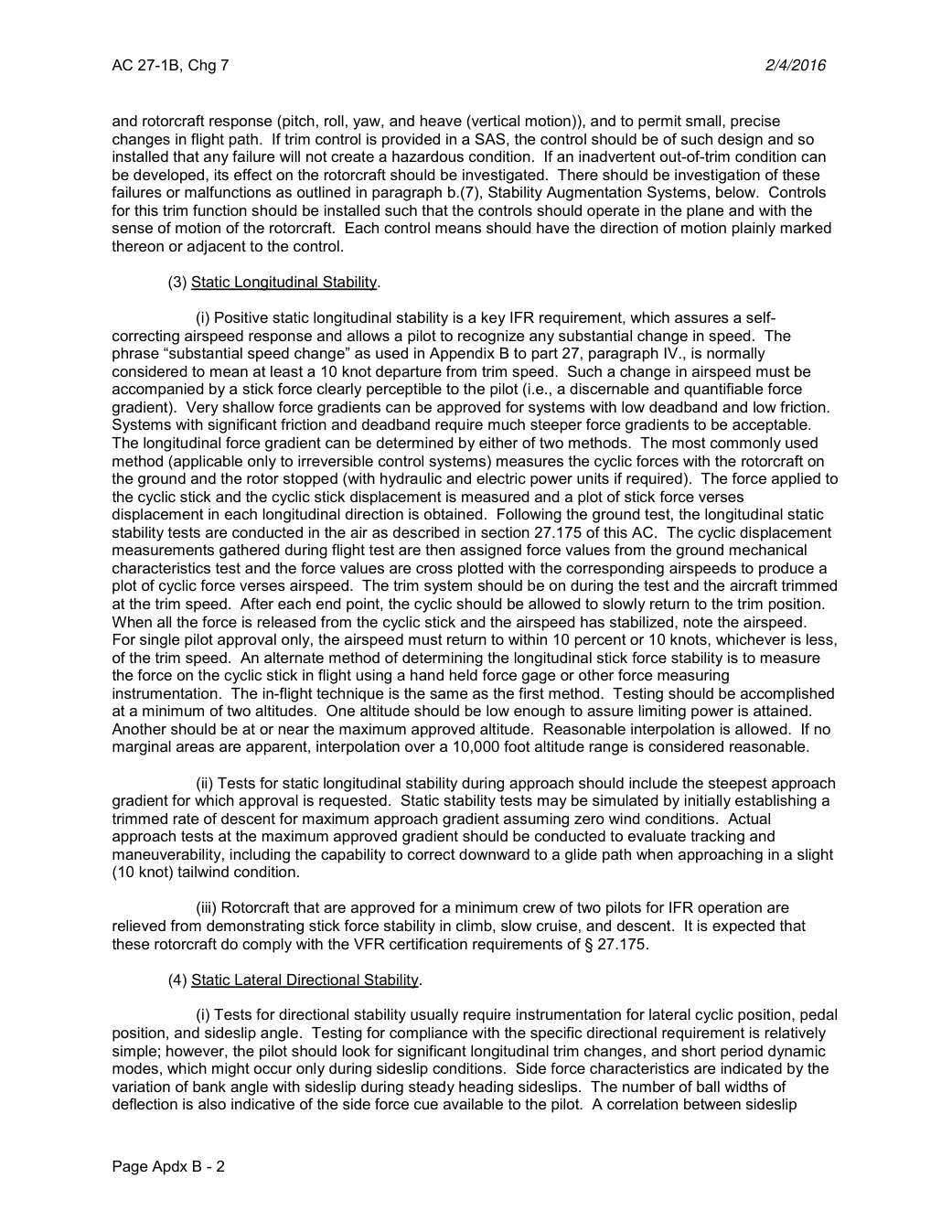
AC 27-1B · Apdx B-2Open saved PDF here ↗
Extracted text for finding words
This extraction supports search. Read the original page for complete notation and layout.
AC 27-1B, Chg 7                                                                       2/4/2016


and rotorcraft response (pitch, roll, yaw, and heave (vertical motion)), and to permit small, precise
changes in flight path.  If trim control is provided in a SAS, the control should be of such design and so
installed that any failure will not create a hazardous condition.  If an inadvertent out-of-trim condition can
be developed, its effect on the rotorcraft should be investigated. There should be investigation of these
failures or malfunctions as outlined in paragraph b.(7), Stability Augmentation Systems, below. Controls
for this trim function should be installed such that the controls should operate in the plane and with the
sense of motion of the rotorcraft. Each control means should have the direction of motion plainly marked
thereon or adjacent to the control.

         (3) Static Longitudinal Stability.

                  (i) Positive static longitudinal stability is a key IFR requirement, which assures a self-
correcting airspeed response and allows a pilot to recognize any substantial change in speed. The
phrase “substantial speed change” as used in Appendix B to part 27, paragraph IV., is normally
considered to mean at least a 10 knot departure from trim speed. Such a change in airspeed must be
accompanied by a stick force clearly perceptible to the pilot (i.e., a discernable and quantifiable force
gradient). Very shallow force gradients can be approved for systems with low deadband and low friction.
Systems with significant friction and deadband require much steeper force gradients to be acceptable.
The longitudinal force gradient can be determined by either of two methods. The most commonly used
method (applicable only to irreversible control systems) measures the cyclic forces with the rotorcraft on
the ground and the rotor stopped (with hydraulic and electric power units if required). The force applied to
the cyclic stick and the cyclic stick displacement is measured and a plot of stick force verses
displacement in each longitudinal direction is obtained. Following the ground test, the longitudinal static
stability tests are conducted in the air as described in section 27.175 of this AC. The cyclic displacement
measurements gathered during flight test are then assigned force values from the ground mechanical
characteristics test and the force values are cross plotted with the corresponding airspeeds to produce a
plot of cyclic force verses airspeed. The trim system should be on during the test and the aircraft trimmed
at the trim speed. After each end point, the cyclic should be allowed to slowly return to the trim position.
When all the force is released from the cyclic stick and the airspeed has stabilized, note the airspeed.
For single pilot approval only, the airspeed must return to within 10 percent or 10 knots, whichever is less,
of the trim speed. An alternate method of determining the longitudinal stick force stability is to measure
the force on the cyclic stick in flight using a hand held force gage or other force measuring
instrumentation. The in-flight technique is the same as the first method. Testing should be accomplished
at a minimum of two altitudes. One altitude should be low enough to assure limiting power is attained.
Another should be at or near the maximum approved altitude. Reasonable interpolation is allowed.  If no
marginal areas are apparent, interpolation over a 10,000 foot altitude range is considered reasonable.

                    (ii) Tests for static longitudinal stability during approach should include the steepest approach
gradient for which approval is requested. Static stability tests may be simulated by initially establishing a
trimmed rate of descent for maximum approach gradient assuming zero wind conditions. Actual
approach tests at the maximum approved gradient should be conducted to evaluate tracking and
maneuverability, including the capability to correct downward to a glide path when approaching in a slight
(10 knot) tailwind condition.

                     (iii) Rotorcraft that are approved for a minimum crew of two pilots for IFR operation are
relieved from demonstrating stick force stability in climb, slow cruise, and descent.  It is expected that
these rotorcraft do comply with the VFR certification requirements of § 27.175.

         (4) Static Lateral Directional Stability.

                  (i) Tests for directional stability usually require instrumentation for lateral cyclic position, pedal
position, and sideslip angle. Testing for compliance with the specific directional requirement is relatively
simple; however, the pilot should look for significant longitudinal trim changes, and short period dynamic
modes, which might occur only during sideslip conditions. Side force characteristics are indicated by the
variation of bank angle with sideslip during steady heading sideslips. The number of ball widths of
deflection is also indicative of the side force cue available to the pilot. A correlation between sideslip


Page Apdx B - 2