Certification of Normal Category Rotorcraft — Changes 1–9
Normal category rotorcraft guidance with Changes 1–9 incorporated. Search the complete AC or start with the system safety, flight controls and instrument-flight guidance.
This source includes guidance for different amendments of Part 27. Match the guidance to the aircraft’s agreed certification basis: the 27.1309 entries for Amendments 27-21, 27-46 and 27-51 are separate. The base AC was issued on 30 September 1999; Change 9 is dated 23 June 2023. The FAA catalogue’s 30 September 2008 date is not the date of the latest change.
The source, within reach.
Search within this AC, jump to a source page, or download the complete saved publication.
This extraction supports search. Read the original page for complete notation and layout.
AC 27-1B, Chg 4                                                     3/31/2014


              (iii) Recoveries from malfunctions should simulate under-the-hood instrument
conditions with an appropriate time delay between pilot recognition of the fault and
initiation of the recovery at all altitudes down to 80 percent of the minimum decision
altitude for which the applicant requests approval.

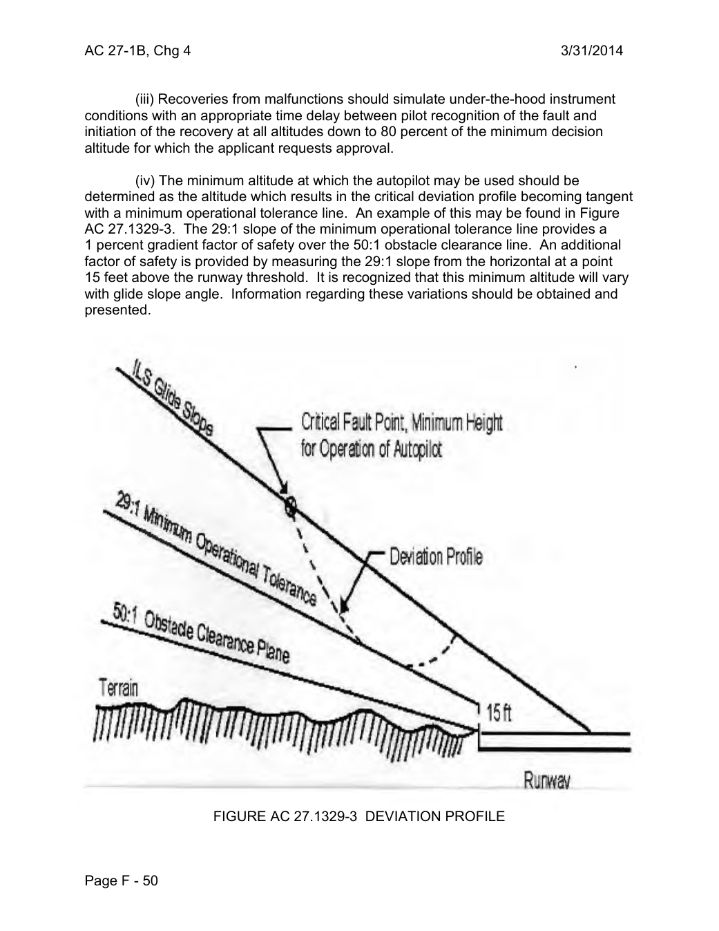
          (iv) The minimum altitude at which the autopilot may be used should be
determined as the altitude which results in the critical deviation profile becoming tangent
with a minimum operational tolerance line. An example of this may be found in Figure
AC 27.1329-3. The 29:1 slope of the minimum operational tolerance line provides a
1 percent gradient factor of safety over the 50:1 obstacle clearance line. An additional
factor of safety is provided by measuring the 29:1 slope from the horizontal at a point
15 feet above the runway threshold.  It is recognized that this minimum altitude will vary
with glide slope angle. Information regarding these variations should be obtained and
presented.


                             er ical Fault·Poin\ Minimum 1-~·ght
                                          tor Operaticn of fiJJtcpilct
     29,


                                                                                        •           •                   •         \\          D~a1ion Profie


                                                                                                            .  ~
                ----·    P~ne


               FIGURE AC 27.1329-3 DEVIATION PROFILE


Page F - 50
Saved from the FAA on November 17, 2026. All original pages are retained. Engineering explanations are presented separately below.
Aerospace Consulting / Engineering perspective
Start with the certification basis and the function.
Identify the applicable amendment before selecting the safety guidance. Connect intended functions and operating conditions to failure conditions, architecture decisions, common-cause considerations, verification and limitations. For flight controls and IFR work, carry the relevant 27.672, 27.1329 and Appendix B assumptions into the system safety and compliance evidence.
1196 original pages. 0 pages have reviewed text reflows. Original-first pages retain the source layout, with extracted text available for finding words.
A focused review, an agreed assessment package or ongoing support alongside your team. We can agree the relevant inputs and scope in the initial conversation.
This opens your email application.
Start a conversation
Tell us about your programme, the system you are developing and the support you need.
We can agree a focused use-case review, a defined evidence package or ongoing programme support.
This opens your email application.
Specialist aerospace expertise
Aerospace Consulting is led by Hussein Khimji, an FAA Designated Engineering Representative in systems and equipment, with a focus on system safety, flight controls and avionics.
We work with aircraft developers and systems suppliers to connect technical decisions, safety assessments and certification evidence.
This is the proposed introduction. The full About page will add your approved biography and associate expertise.
Systems engineering & development assurance
Tell us about the aircraft or system, its intended function, stage of development and the support you need.